


Overview
This manual is the RF test manual of WiFi Module USR-WIFI232-B2, which includes the test preparation and test procedure.
1.Test preparation
1.1.Hardware connection
Hardware connection diagram as follow:
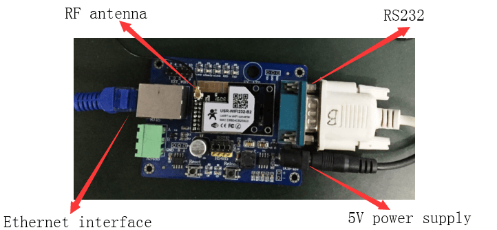
Connect RF antenna and 5V power adapter to module. Connect B2’s RS232 interface and Ethernet interface to PC directly.
1.2.Software
- WinPcap.exe
- QATool_Dbg.exe
- Serial port software(Such as USR-WIFI232-Setup.exe to send AT commands)
2.Test procedure
Step 1: Install WinPcap.exe on PC firstly.
Step 2: Complete hardware connection in 1.1.Hardware connection and run the serial port software USR-WIFI232-Setup.exe.
Step 3: Enter AT command mode and send following AT commands.
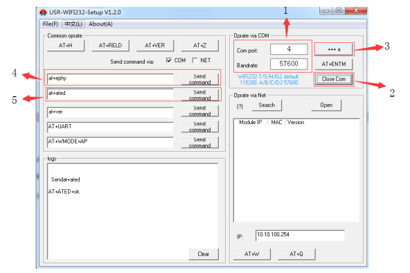
- correct Com port and baud rate.(Default baud rate of B2 is 57600)
2.Click ‘Open Com’ to open Com port and software displays ‘Close Com’ means opening Com port successfully.
3.Click ‘+++a’ to enter AT command mode. Left bottom part of software- ’logs’ returns ‘a+ok’ means module entering AT command mode.
4.Send command ‘AT+EPHY’. Left bottom part of software- ’logs’ returns ‘AT+EPHY+OK’ means ‘AT+EPHY’ command configuring module successfully.
5.Send command ‘AT+ATED’. Left bottom part of software- ’logs’ returns ‘AT+ATED+OK’ means ‘AT+ATED’ command configuring module successfully.
Now Ethernet interface of PC will display establishing connection successfully.
Step 4: Run software QATool_Dbg.exe and finish following steps to enter software parameters interface.
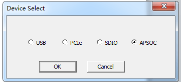

 Choose ‘APSOC’ and click ‘OK’.
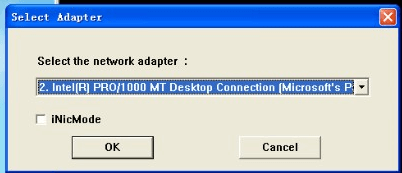

 Choose correct network adapter and click ‘OK’.
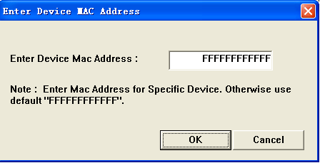
Click ‘OK’ to continue.
Step 5: Enter following software interface and configure related parameters.
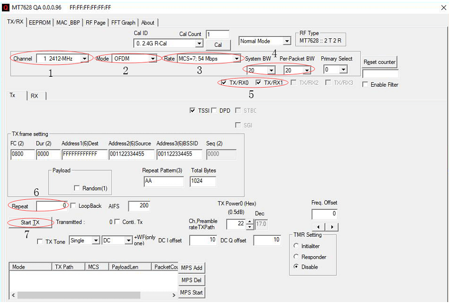
 1.Channel: Choose 2412MHz.
2.Mode: 11b/g/n option.
3.Rate: Rate level option.
4.Bandwidth option.
5.Choose TX0/RX0.
6.Repeat: Modify to 0.
7.Click ‘Start TX’ button to start RF test.


