In energy storage cabinet projects, the real challenge often lies not in installing batteries and PC into the cabinet, but in how the equipment, after being delivered to the site, integrates and coordinates with photovoltaic systems, wind power systems, and the existing power distribution system of the station.
This is particularly true for projects such as schools, hospitals, mines, and charging stations, where electricity consumption patterns are entirely different. Some have abundant solar power during the day and low load at night, some require stable power supply 24/7, and others experience significant instantaneous power during peak charging periods. If an energy storage cabinet only charges and discharges at fixed times, it can hardly realize its full potential. For manufacturers, this inevitably leads to a crucial question: how to uniformly integrate data from so many on-site devices and how to perform dispatch based on actual supply and demand.
The first challenge is the lack of standardized communication among devices.
Devices like PV inverters, wind turbine controllers, hydropower equipment, electricity meters, PC, BMS, and power distribution equipment from different manufacturers often have inconsistent communication interfaces and protocols. While each device may function correctly when tested individually, integrating them into a single project requires redefining data point lists, communication addresses, and refresh cycles.
The second challenge is the rapid variability of energy sources.
PV generation is affected by weather, wind power by wind speed, and loads are not constant either. Taking a charging station as an example, when several high-power charging piles start simultaneously, the load can surge rapidly within a short time. If the energy storage system cannot promptly acquire data from the generation side, the storage side, and the load side, it becomes difficult to achieve peak shaving, demand limitation, or prioritized consumption of renewable energy.
The third challenge is the risk of over-reliance on the central platform for all control functions. Once the external network is interrupted, if the EMS can only rely on cloud-delivered strategies, the on-site energy storage system loses its regulation capability. Therefore, when designing systems, manufacturers usually need to consider local data acquisition, local strategies, and independent operation after network disconnection.
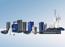
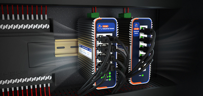
For such projects, the system can be simply understood as having two layers: the industrial switch USR-ISG is responsible for networking the devices, while the Fanless Industrial PC USR-EG628 is responsible for on-site data acquisition, strategy calculation, and control.
On-site devices such as PV inverters, wind turbine controllers, hydropower or other power source equipment, as well as PCS, BMS, electricity meters, and environmental monitoring devices, are first connected to the USR-ISG Industrial Switch to form the internal communication network of the energy storage cabinet or microgrid. The USR-ISG series offers models with Fast Ethernet/Gigabit Ethernet, 5/8 ports, etc., and adopts industrial designs featuring wide temperature range and dual power supplies, making it suitable for installation inside control cabinets.
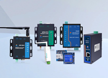
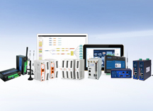
After data aggregation, it is then fed into the Fanless Industrial PC USR-EG628. The Fanless Industrial PC EG628 provides interfaces such as Ethernet, RS485, RS232, and CAN, and supports protocols including Modbus, OPC UA, IEC104, and IEC61850. It can be used for data access and protocol adaptation of different field devices.
The entire link can be summarized as:
Power Sources (PV/Wind/Hydro/Grid, etc.) → Inverters & Control Equipment → USR-ISG → USR-EG628 → PCS/BMS/Energy Storage System → Loads
(Schools, Hospitals, Mines, Charging Stations, etc.).
Real-world projects may not involve all energy sources like solar, wind, hydro, and thermal simultaneously; instead, they connect based on the existing energy conditions of the station. The role of energy storage is to add an adjustable buffer between the power sources and the loads.
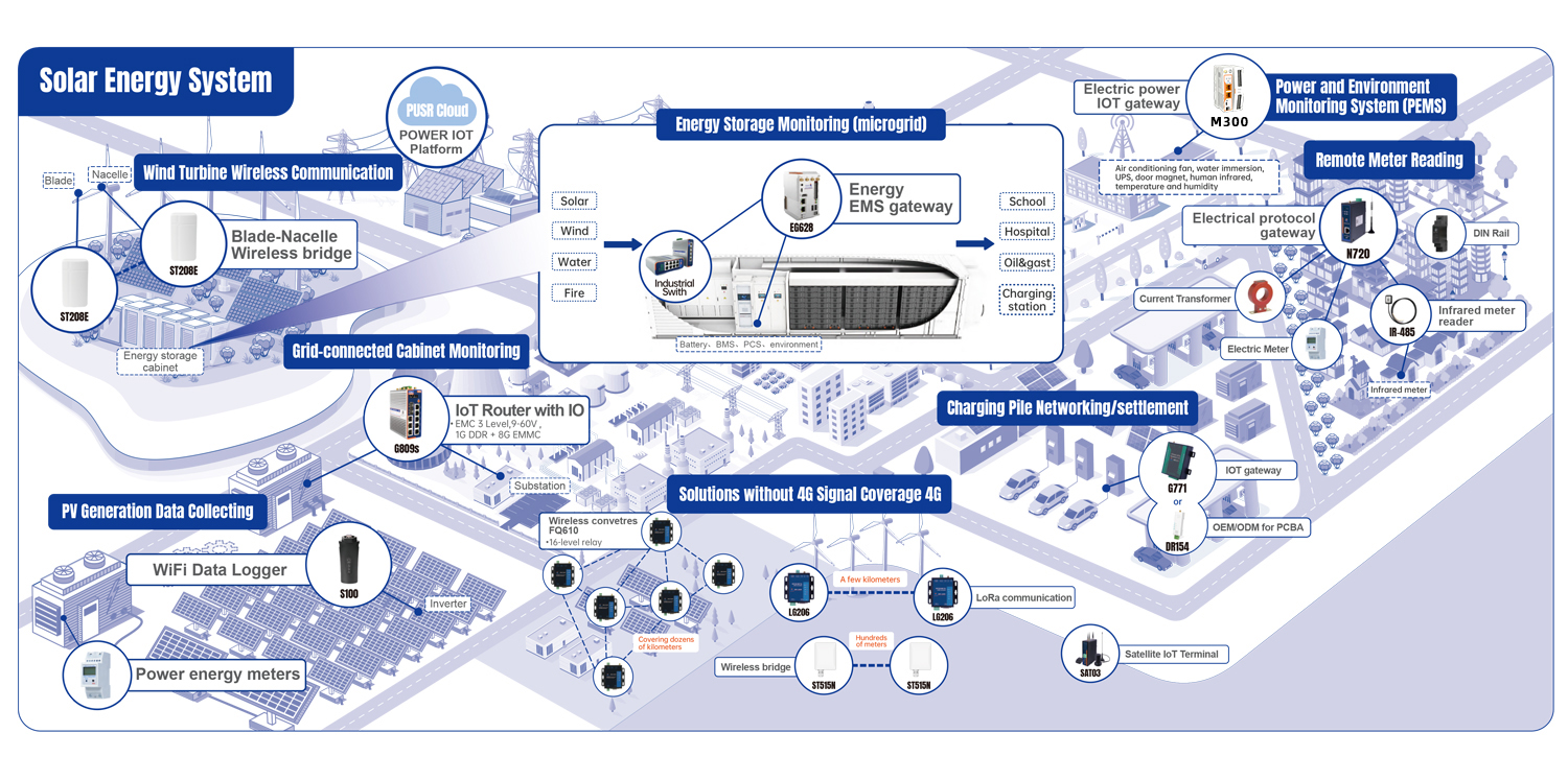
Taking a "PV + Energy Storage + Charging Station" project as an example, the Fanless Industrial PC EG628 continuously reads PV generation power, grid power, energy storage SOC, PCS status, and the total load of charging piles.
When PV generation is high at noon and exceeds on-site consumption, the energy storage can be charged according to the EMS strategy. In the evening, when charging vehicles increase and the load rises, the energy storage releases part of its energy to reduce the instantaneous power drawn from the grid side. If the SOC has already reached the set lower limit, further discharge is stopped to retain necessary backup capacity.
The logic differs for hospitals and schools. Hospitals prioritize power supply reliability and cannot simply deplete the battery for peak shaving. Mines may be more concerned about load fluctuations caused by the startup of large equipment. PV-Storage-Charging stations focus more on PV consumption and peak charging periods.
Therefore, so-called "intelligent regulation" is not a fixed algorithm. It involves uniformly collecting data from sources, the grid, loads, and storage, and then executing different strategies on-site based on the actual project requirements. The Fanless Industrial PC EG628 supports local edge acquisition, computation, and active reporting, enabling the execution of partial logic on-site, rather than requiring all data to be uploaded to the cloud for processing.
The most common issue arises from the lack of unified data point lists in the early stages. Before equipment arrives on-site, it is best to finalize the protocols, IP addresses, registers, and control permissions for inverters, PCS, BMS, electricity meters, and power distribution equipment. Otherwise, a significant amount of time will be spent on joint debugging later.
The second point is to separate "monitoring/control" from "protection". The Fanless Industrial PC EG628 is suitable for EMS-level data acquisition, energy strategy, and linkage control, but it cannot replace the inherent safety protection functions of devices like PCS, BMS, and protective relays. Safety logic for overvoltage, overcurrent, insulation, and fire protection should still be independently handled by the respective devices.
The third point is to build redundancy into the network. When there are numerous energy storage cabinets or the site spans a large area, it is advisable to reserve expansion capacity for switch ports, network bandwidth, and link topology during the design phase. Some models of the USR-ISG support different configurations like optical ports, PoE, and ring networks. Selection should be based on the actual network structure, rather than applying one model to all projects.
Finally, it is essential to conduct tests for network disconnection, power failure, and device abnormalities. Can the system still operate according to local strategies after the uplink network is disconnected Will the communication failure of one inverter affect other devices Can the EMS correctly identify a PC shutdown These scenarios are more revealing of the system's true on-site operational capability than simply checking if "data can be uploaded" during normal operation.
For energy storage cabinet manufacturers, microgrid projects ultimately are not just about connecting more devices to a single platform. The core is first to integrate data from the power source side (PV, wind, etc.), the storage side, and the load side (schools, hospitals, mines, charging stations), and then to retain the regulation capability on-site. Industrial switches solve the connectivity problem, and fanless industrial PCs solve the data and strategy problems. Only when combined can an energy storage cabinet evolve from a simple charge/discharge device into a truly adjustable node within the entire microgrid.