In new energy projects such as photovoltaic (PV) and wind power, communication conditions often have no direct correlation with project scale. Regions like mountainous areas, Gobi deserts, tidal flats, and water surfaces usually boast superior new energy resource conditions, but they often suffer from poor operator network coverage.
In the early construction stage of many projects, the focus is heavily placed on modules, inverters, and grid-connected equipment. It is not until the later stage, when systems for remote monitoring, environmental monitoring, video security, and intelligent inspection need to be connected, that a very practical problem emerges: the equipment is fully installed, but there is no 4G signal, making on-site data transmission impossible.
A large volume of operational data is generated daily by equipment in PV power stations, including inverters, combiner boxes, electricity meters, meteorological stations, and pad-mounted transformers.
If a remote subarray is located in a 4G blind spot, the equipment itself may still generate power normally, but the real-time status cannot be viewed on the backend. Once issues such as inverter shutdown, string abnormality, or environmental monitoring device disconnection occur, they can only be detected when operation and maintenance personnel arrive on site.
This problem becomes even more prominent for large-scale mountain PV stations and centralized power stations. Several monitoring points may be separated by several kilometers or even more than ten kilometers, with hills, roads, or PV arrays in between. If optical fibers were not reserved in the early design stage, the cost of re-ditching and pipe threading in the later stage is usually very high.
Therefore, the solution to 4G blind spots is not necessarily to "find a way to get 4G signal at every equipment point". A more practical approach is: First, use the internal wireless communication of the power station to transmit data from the blind spot to a location with network access, and then upload the data to the platform via 4G, optical fiber, or dedicated line.
Based on different communication distances and service data types, the on-site scenarios can be roughly divided into three categories.
Mountain PV stations and Gobi centralized power stations can have a depth of up to more than ten kilometers. In this case, it is not recommended to simply "use one device to cover a dozen kilometers directly".
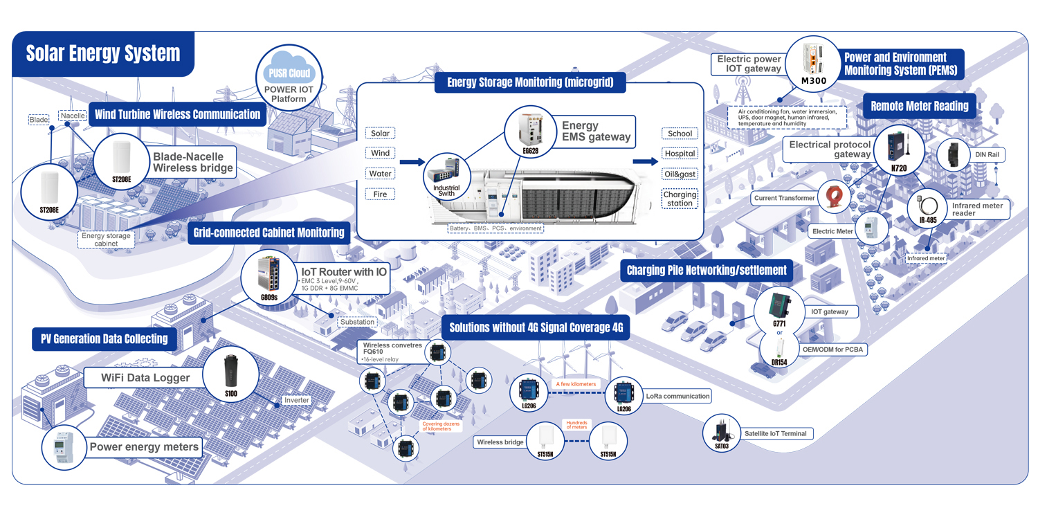
A more reasonable method is to deploy Wireless Swarm Converter USR-FQ610 to establish a wireless ad-hoc network inside the power station, set up communication nodes in different areas, and use multiple node relays to transmit remote data step by step to the central control room or a location with public network egress.
For example: Remote subarray equipment → FQ610 node → Relay node → Relay node → Central control room → 4G/Fiber → Cloud platform
The advantage of this solution is that the farthest end does not need to be directly covered by the operator's base station. As long as a stable link can be established between the internal nodes of the power station, data can be gradually aggregated and transmitted out.
During deployment, the location of relay points is more critical than simply pursuing maximum transmission distance. Mountain backslopes, forests, and equipment rooms will all affect wireless propagation. Therefore, nodes should not be arranged evenly only according to the map distance, but should be tested and adjusted based on the on-site terrain.
Meanwhile, it should be noted that the Wireless Swarm Converter FQ610 is responsible for the internal wireless link of the power station, and cannot be simply equated with an industrial 4G router. The final aggregation point still needs to upload data through an existing industrial 4G router, optical fiber, or other public network egress.
If the devices to be networked are distributed within a range of several kilometers, and the main transmitted contents are small-data-volume information such as electricity meter data, environmental parameters, equipment status, and alarm messages, LoRa is a more appropriate choice.
For example, using the LoRa Modem USR-LG206, RS485 or RS232 devices can be connected at each remote point, and data can be transmitted to the central node via LoRa.
A typical link is: Electric Meter/Sensor → LG206 → LoRa → Central-end LoRa Modem LG206/Gateway → Data Acquisition Device → Monitoring System
Point-to-point topology can be adopted when there are few devices, and point-to-multipoint topology is suitable for scenarios with scattered points. This solution is especially ideal for adding data collection points for meteorological monitoring, electricity meters, and sensors in old power stations that did not reserve communication lines.
However, LoRa is not a high-bandwidth network. It is more suitable for small data, periodic data, and status information, and is not designed for transmitting camera videos or large files.
During on-site installation, antenna height, mountain obstruction, and frequency band interference should be prioritized. Meanwhile, select an appropriate operating frequency band in accordance with local radio management regulations. The LoRa Modem LG206 is certified with CE, FCC, RCM, RoHS, WEEE, and WPC, but specific projects still need to be used in compliance with local regulations and on-site conditions.
If the communication distance is only a few hundred meters, for example, between two PV arrays, between the convergence area and the equipment room, or between the control room and nearby cameras, where trenching and wiring are inconvenient, the ST515N wireless bridge can be used.
The deployment method is relatively simple: On-site PLC/Switch/Camera → ST515N → Wireless → ST515N → Switch → Central Control System
One bridge is installed at each end to complete the point-to-point connection, which is equivalent to replacing the intermediate network cable segment with a wireless link.
Compared with LoRa, the wireless bridge has higher bandwidth, so in addition to equipment data, it is also more suitable for video surveillance, PLC networks, and other Ethernet services.
However, wireless bridges are highly dependent on line-of-sight environments. PV modules themselves have a large number of metal frames and brackets. If the antenna is installed too low, it is easily blocked by the arrays. Therefore, it is generally recommended to install the equipment above the upper edge of the modules or in a relatively open position to ensure maximum direct visibility between the two ends.
When the Wireless Swarm Converter FQ610 is used to solve large-scale networking problems, the priority is node planning. Do not design the link to its theoretical limit based on the product's nominal distance, and reserve sufficient margin according to the actual terrain. Wireless equipment installed at commanding heights also needs to be equipped with lightning protection, grounding, and surge protection measures.
When deploying the LoRa Modem LG206, the focus is on frequency band planning and antenna environment assessment. It is best to test the on-site wireless environment before formal construction, and do not blindly increase the transmission power just to pursue longer distance. In complex power stations, channel planning between multiple nodes is far more critical.
For ST515N deployment, the core requirements are unobstructed visibility and link stability. After the two ends are connected, do not only verify basic connectivity via "Ping test". It is recommended to continuously observe the signal strength, packet loss rate, and actual service data for a period of time. If it is used for video surveillance, the stability under continuous transmission must be fully verified. The ST515N has CE and RoHS certifications, but outdoor installation still requires proper interface waterproofing, equipment fixation, and lightning protection treatment.
When new energy power stations encounter 4G blind spots, the most common misconception is to keep trying higher-gain 4G antennas.
However, if the site is very far from the base station or located on the backslope of a mountain, it is impossible to obtain a stable network no matter how the terminal is adjusted.
A more practical approach is to split the communication link according to the distance: For large power stations spanning more than ten kilometers, use ad-hoc network nodes such as the Wireless Swarm Converter FQ610 for step-by-step relay; for small data collection within several kilometers, use LoRa Modem LG206 for LoRa communication; for Ethernet and video transmission within hundreds of meters, use the ST515N wireless bridge.
Wireless communication is not designed to replace optical fibers, network cables, or 4G. Instead, it reliably transmits on-site data in locations where these wired solutions cannot reach, are too costly, or are difficult to construct.
For the retrofit of existing PV power stations, this solution is often more practical than large-scale re-ditching and wiring. For new projects, the wireless link can also be considered as an integral part of the communication network in the design stage, leaving more space for adding monitoring points and intelligent operation and maintenance equipment in the future