1.Configure H3C WSR 800-10
1.1.Enter H3C WSR 800-10 Web Server
Power the H3C WSR 800-10 and connect PC Ethernet interface to H3C WSR 800-10 GE2 interface. Because H3C WSR 800-10 IP is 192.168.1.1, user can configure PC IP address to 192.168.1.2 as follow:
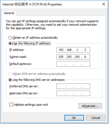
Figure 1 Modify PC to static IP address
After above configuration, open browser and enter H3C WSR 800-10 Web Server(192.168.1.2). Username and password of Web Server both are admin. User can also change language in login web page.
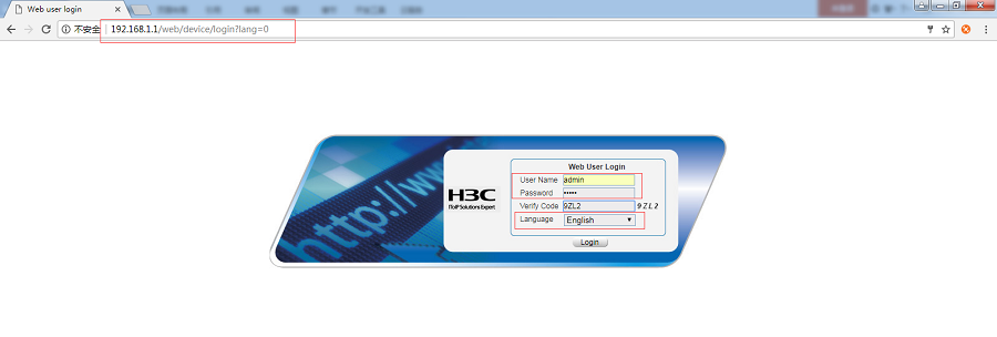
Figure 2 Login Web Page
1.2.Configure VPN Server parameters
After entering Web Server, user can configure VPN Server parameters.
1.2.1.Create L2TP user group
Choose ‘System Management > Users’ in left line and click ‘Create User’. Then user should change parameters as follows:
Username: usrtest
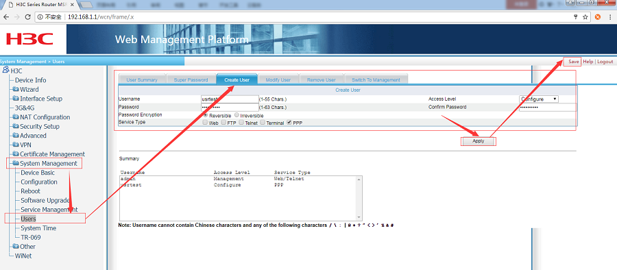
Figure 3 Create L2TP user group
After changing, don’t forget applying and saving parameters.
1.2.2.Enable L2TP
Choose ‘ VPN > L2TP > L2TP Config’ in left line and choose ‘Enable L2TP’. Then apply and save parameters as follow:
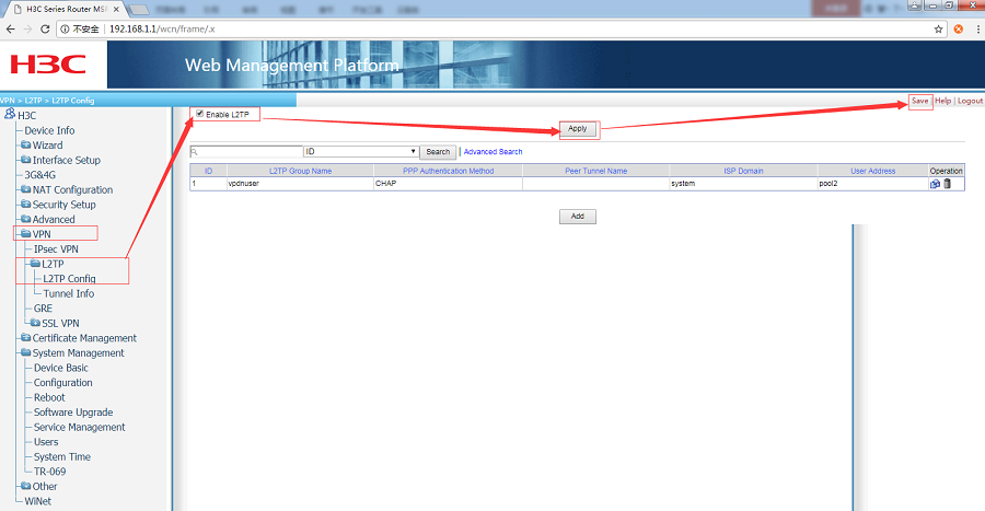
Figure 4 Enable L2TP
1.2.3.Modify PPP authentication method of ISP domain system
Choose ‘ VPN > L2TP > L2TP Config’ in left line and click ‘Add’.
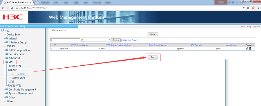
Figure 5 Add new group
After clicking ‘Add’, user will into L2TP Group configuration web. In this web, user should configure ‘Authentication Method’ as ‘CHAP’ and ‘ISP Domain’ as ‘system’, then click ‘Modify’ as follow:
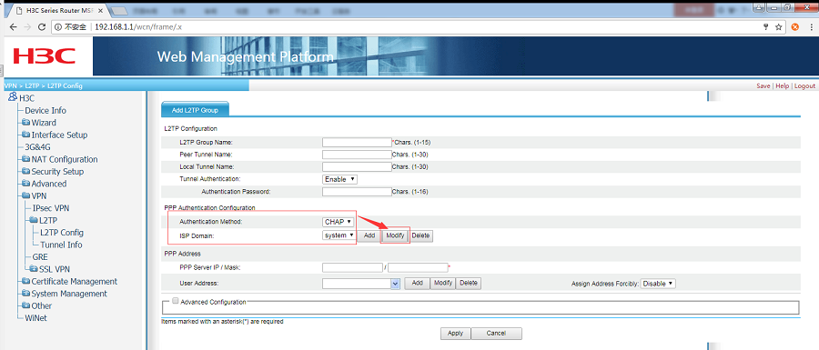
Figure 6 Configure Authentication Method and ISP Domain
After clicking ‘Modify’ in above web page, user will into ISP Domain configuration web and user should choose ‘Local’ as primary server type of PPP authentication method, then click ‘Apply’ and return to L2TP Group configuration web page.
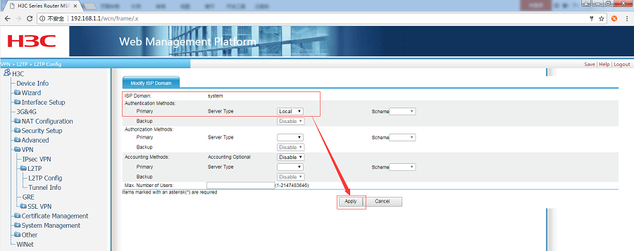
Figure 7 Configure PPP server type
1.2.4. Configure IP Address Pool
In L2TP Group configuration web, click ‘Add’ after ‘User Address’ to enter IP address pool configuration web. After entering IP address pool configuration web, configure parameters as follows:
ISP Domain: system
After configuring IP address pool, click ‘Apply’ and return to L2TP Group configuration web page.
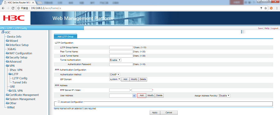
Figure 8 Add new address pool
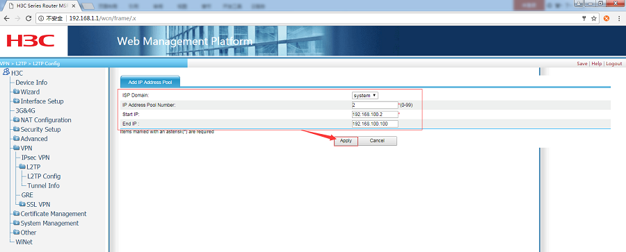
Figure 9 Configure address pool
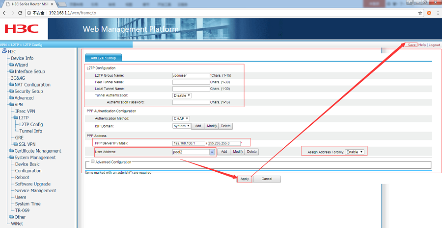
Figure 10 Configure L2TP group
1.3.Other configurations
1.3.1.Configure WAN/LAN interface
After configuring VPN Server parameters successfully by 1.2.Configure VPN Server parameters, to establish VPN tunnel, PING successfully between IP is also needed. It has no relation to IP is public network IP or LAN IP. This test is in LAN, so it needs to configure WAN interface to DHCP to get IP address from superior router automatically. User should enter WAN/LAN interface configuration web page and change parameters as follows:
Firstly, change WAN interface GE0 interface parameters:
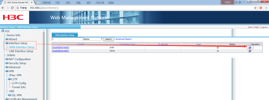
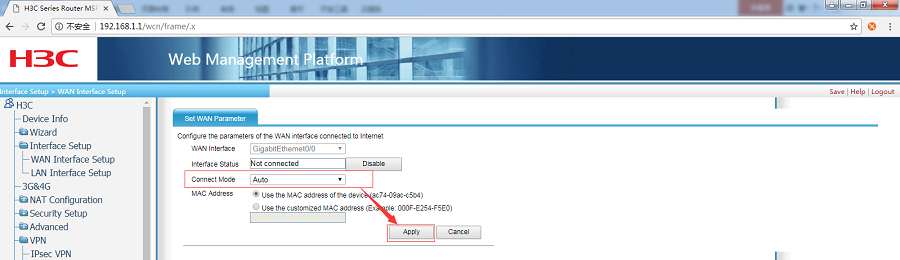
Figure 11 Configure WAN interface
Then change LAN interface parameters:
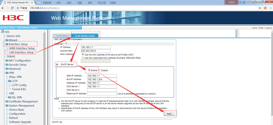
Figure 12 Configure LAN interface
After configuring, click ‘Save’ to save current settings.
1.3.2.NAT Configuration
Modify NAT configuration as follow:
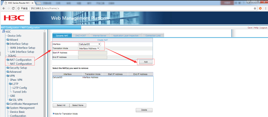
Figure 13 Configure NAT
1.3.3.Route Setup
Configure ‘Route Setup’ as follow:
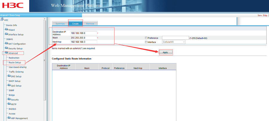
Figure 14 Configure Route Setup
Destination IP Address: G806’s device IP. G806’s LAN interface IP is 100.100.100.1, so set to 100.100.100.0 can communicate to all device connect to G806 LAN interface.
Next Hop: G806 VPN IP address. User can know G806 VPN IP as follow:
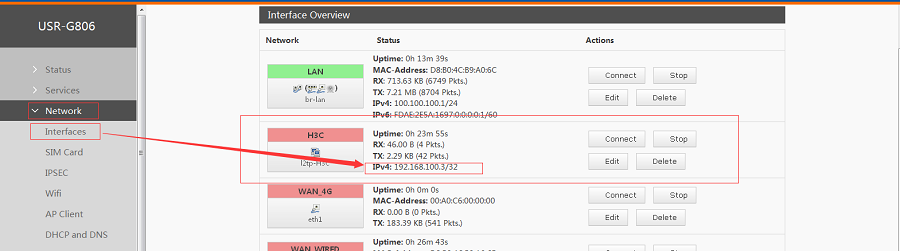
Figure 15 G806 VPN IP
Note: Don’t forget click ‘Save’ to save settings after configuring all parameters.
2.Configure G806
2.1.Enter G806 Web Server
If G806 is in default parameters, the Web Server IP is 192.168.1.1. Connect PC to G806 LAN interface and configure PC into DHCP mode as follow:
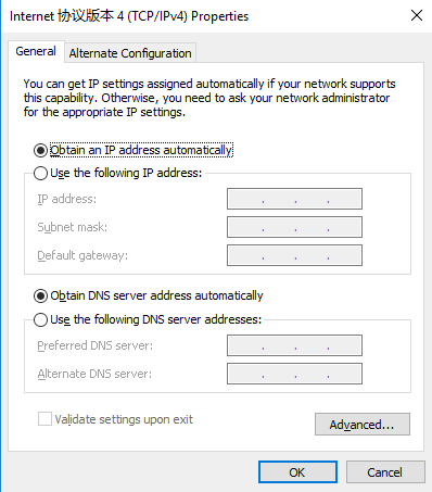
Figure 16 Set PC to DHCP mode
Then enter 192.168.1.1 and login with username and password both are root.
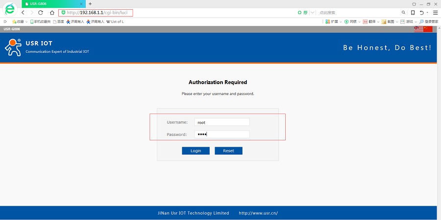
Figure 17 Enter G806 Web Server
2.2.Configure G806 VPN interface
2.2.1.Modify G806 LAN interface IP
After entering G806 Web Server, if G806’s LAN interface IP in same network segment as H3C’s LAN interface or superior router’s LAN interface(Superior router will assign to G806 a IP as G806’s WAN interface according to own LAN interface IP and G806 can’t have LAN/WAN interface in same network segment), user should change G806 LAN interface IP address. H3C’s LAN interface is 192.168.1.1 too, so we set G806’ LAN interface IP address to 100.100.100.1 as follows:
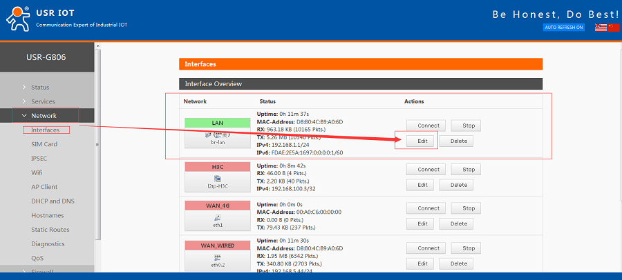
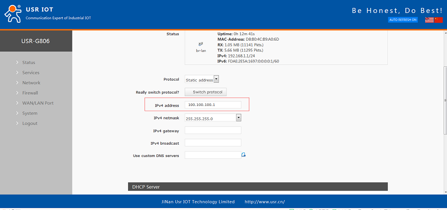
Figure 18 Modify LAN interface IP
After modifying to 100.100.100.1, user should click ‘Save&Apply’ on bottom of web page to make settings take effect. And user also needs to enter Web Server by 100.100.100.1 again.
2.2.2.Add VPN interface
After configuring LAN interface successfully, user can start configuring VPN parameters.
Firstly, add a new interface with protocol ‘L2TP’ as follows:
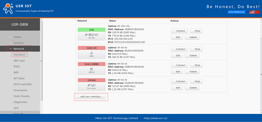
Figure 19 Add VPN interface
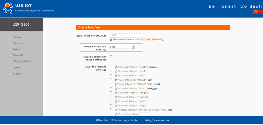
Figure 20 Configure new VPN interface
After writing name and choosing correct protocol, user should click ‘Submit” on bottom of web page to continue configuring.
In ‘General Setup’, user should configure parameters as follows:
L2TP Server: 192.168.5.73(We take LAN test as a example, so we write H3C’s IP address from superior router here. In actual use, user should use public network IP address or domain name)
PAP/CHAP username: usrtest(Same as H3C VPN settings)
PAP/CHAP password: www.usr.cn (Same as H3C VPN settings)
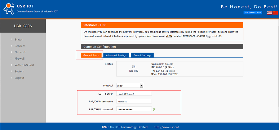
Figure 21 Configure General Setup of VPN interface
In ‘Firewall Settings’, user should configure as follow:
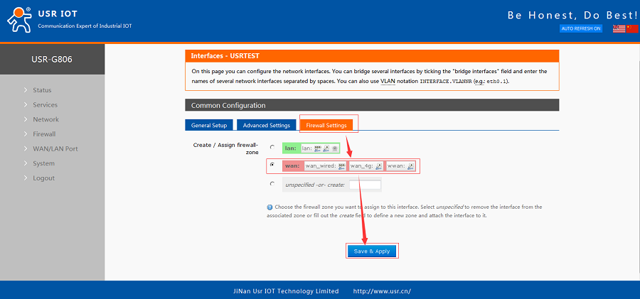
Figure 22 Configure Firewall Settings of VPN interface
2.2.3.Configure Static Routes
After above configuring, G806 and H3C can ping each other successfully, but to achieve communication between two router’s device, user should configure ‘Static Routes’. Firstly, add new static route as follow:
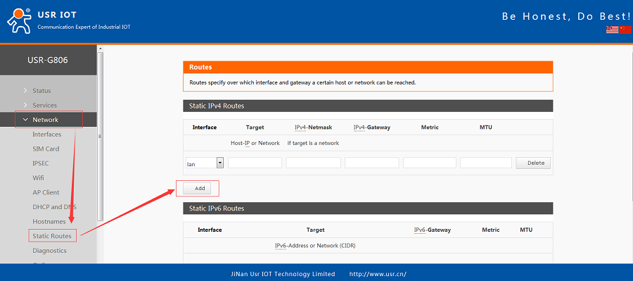
Figure 23 Add new Static Route
Then configure the new route as follows:
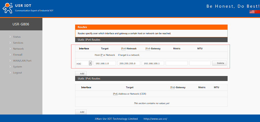
Figure 24 Configure the new static route
After modifying parameters, click ‘Save&Apply’.
2.2.4.Configure Firewall
User also needs to configure ‘Firewall’ parameters as follows:
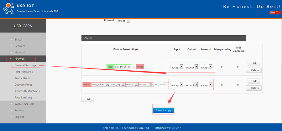
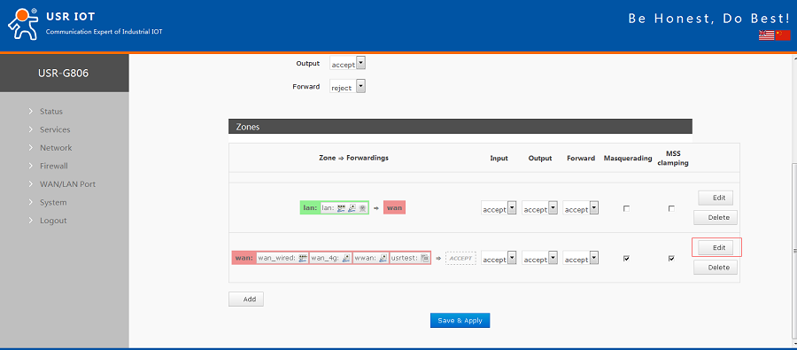
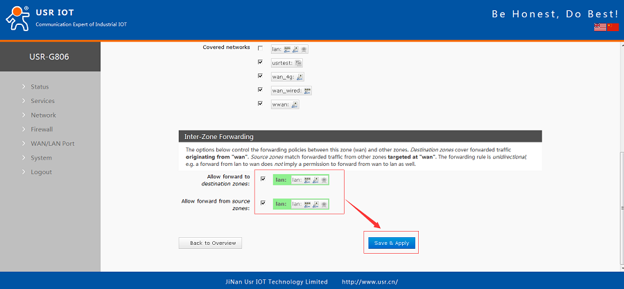
Figure 25 Configure Firewall
After above all configuration, user can connect G806 and H3C to a same superior router and ping successfully between H3C’s device and G806’s device as follow:
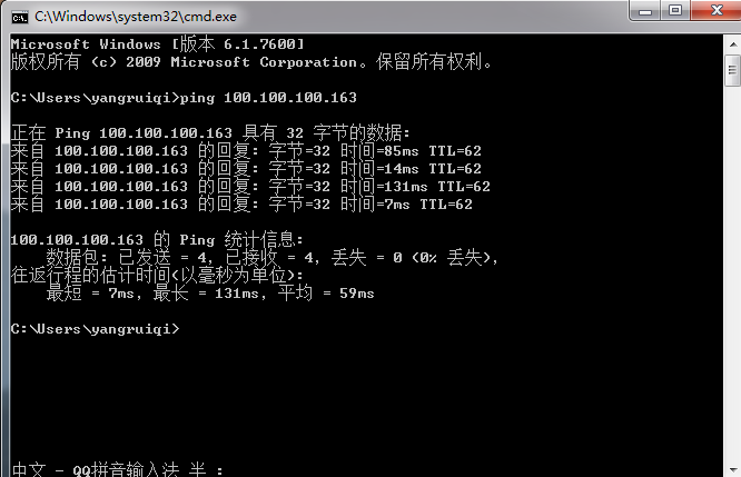
Figure 26 Ping successfully