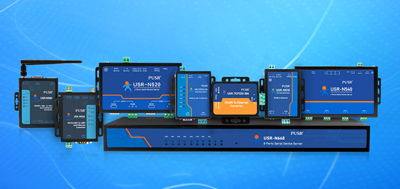
In photovoltaic operation projects, the RS485 to Ethernet Converter serves as the critical bridge connecting solar inverters to supervisory monitoring systems. This article explains how to properly configure a Modbus gateway so that data from multiple inverters on an RS485 bus can be uploaded reliably via Ethernet.
RS485 to Ethernet converters on the market typically offer two operating modes:
Transparent transmission modehandles data forwarding only, without protocol parsing. The device simply relays Modbus RTU frames received on the RS485 side to the Ethernet network, and vice versa. This mode is suitable for simple point-to-point communication scenarios.
Modbus Gateway mode(RTU-to-TCP conversion) provides protocol awareness. The device can parse Modbus frame structures, perform RTU-to-TCP protocol translation, and support slave address mapping, polling management, and error data filtering. For photovoltaic monitoring systems with multiple inverters, this mode is the better choice.
In a typical solar power plant, 10 to 20 inverters share a single RS485 bus. Data from all inverters converges through the RS485 to Ethernet Converter and communicates with the host system via a single TCP connection.
Wiring essentials:
In actual deployments where the RS485 bus exceeds 1200 meters, an industrial-grade converter with signal amplification is recommended.
Using the PUSR USR-TCP232-410s serial server as an example, here are the configuration steps.
The USR-TCP232-410s features dual serial ports (RS232 + RS485), 5~36V DC wide-voltage power supply, and operates within a -40℃ to +85℃ industrial temperature range. Connect the inverter RS485 bus to the device's RS485 port (A+, B-), and connect the Ethernet port to the on-site switch.
The device supports 1.5KV electromagnetic isolation, which effectively suppresses electromagnetic interference in photovoltaic environments and ensures data transmission stability.
Use the web management interface or configuration software to set the device's IP address, subnet mask, and gateway. Ensure the converter's IP address is on the same subnet as the host system.
Select the operating mode as "Modbus Gateway" or "RTU-to-TCP Conversion" in the device interface. Key parameter settings:
Use tools like Modbus Poll to connect to the converter's IP address on port 502, and read data from each slave address one by one. Confirm that the register values returned by the inverters match the specifications on the device nameplates.
Inverter data not updating: Check RS485 bus wiring to ensure A/B lines are not reversed; verify that slave addresses and inverter register addresses match.
Frequent communication timeouts: Shorten the polling interval, increase the timeout value, and confirm terminating resistors are properly installed.
Some inverters unresponsive: Disconnect inverters one by one to identify faulty devices; ensure the RS485 bus does not exceed the 32-device limit specified by the protocol. Add repeaters if necessary.
In photovoltaic systems with 10 to 20 inverters, using transparent transmission mode requires each inverter to establish an independent TCP connection with the host system, significantly increasing server load.
Modbus Gateway mode optimizes communication through:
For photovoltaic monitoring projects requiring long-term stable operation, enabling Modbus Gateway mode is the more reliable approach.
1. What is the difference between an RS485 to Ethernet Converter and a Modbus Gateway?
RS485 to Ethernet Converter is the generic term for the hardware device that converts RS485 serial signals to Ethernet signals. Modbus Gateway is an operating mode of the device that provides Modbus protocol parsing and translation capabilities. Most industrial-grade converters support both transparent transmission and Modbus Gateway modes.
2. Can Modbus RTU and Modbus TCP communicate directly?
No. Modbus RTU is based on serial communication (RS485/RS232) using 7-bit or 8-bit data frames. Modbus TCP is based on Ethernet TCP/IP protocol and uses TLV encoding. The two protocols have completely different structures and physical layers, requiring a Modbus gateway for protocol translation.
3. How many inverters can be connected to one RS485 bus?
A standard RS485 bus supports up to 32 device nodes. Using half-isolated RS485 repeaters can extend this to 64 devices, and fully isolated optocoupler repeaters allow further expansion. In actual deployments, bus length (no more than 1200 meters) and cable quality must also be considered.
4. How should the polling interval of a Modbus Gateway be set?
The polling interval depends on the number of inverters and the host system's processing capacity. For systems with 10 to 20 inverters, a polling interval of 50~100ms is recommended. If data update frequency requirements are relaxed (e.g., once per second), the polling interval can be extended to 200ms or longer to reduce network load.
5. Does the RS485 bus require terminating resistors?
Yes. Installing a 120Ω terminating resistor at both ends of the RS485 bus (start and end) eliminates signal reflection at the bus end and improves communication stability. Terminating resistors are essential when the bus length exceeds 300 meters or when the communication rate is higher than 19200bps.
6. How to choose between transparent transmission mode and Modbus Gateway mode?
If only 1 to 2 devices need to communicate and the host system supports direct Modbus RTU protocol, transparent transmission mode can be chosen for its simple configuration. If multiple slave devices are involved and polling management or reduced host complexity is needed, Modbus Gateway mode should be selected.
7. Do converters support IoT protocols such as MQTT?
Some industrial-grade RS485 to Ethernet Converters support IoT protocols such as MQTT and Modbus TCP-to-MQTT conversion, allowing collected data to be uploaded directly to cloud platforms. For photovoltaic projects requiring remote monitoring, this feature can reduce the deployment of intermediate-layer equipment.
8. How to troubleshoot RS485 communication failures?
The following steps are recommended: (1) Confirm A/B line wiring is correct; (2) Check whether terminating resistors are installed; (3) Use a multimeter to measure the RS485 bus voltage differential (normal value should exceed 200mV); (4) Disconnect inverters one by one to identify faulty devices; (5) Check the converter indicator lights (RUN, LINK, TX/RX should blink normally).