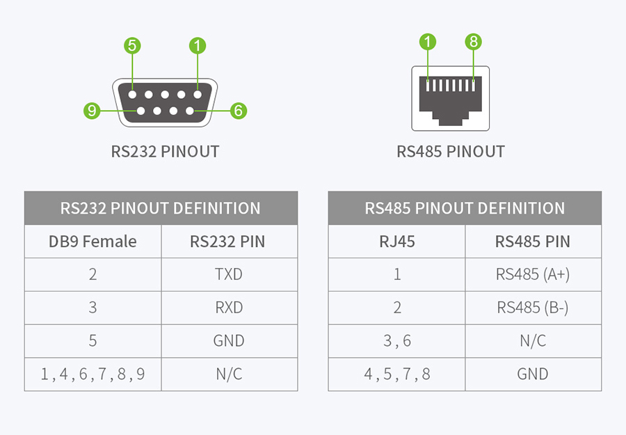
RS485 interface is a half-duplex, balanced transmission communication interface, which is widely used in industrial automation, intelligent transportation, intelligent building and other fields. It is based on differential signal transmission and has strong anti-interference capabilities, making data transmission more stable and reliable. RS485 interface usually uses a pair of twisted-pair cables for transmission, with a maximum transmission distance of up to 1200 meters.
RS485 communication adopts a differential signal negative logic control mode, where 2-6V represents "0" and -6-2V represents "1". RS485 communication has two wiring modes: two-wire system and four-wire system. The four-wire system can only achieve point-to-point communication, and is now rarely used. The two-wire system wiring method is currently the most commonly used bus topology structure, which is a half-duplex transmission method, meaning that the transmission and reception are not synchronized.
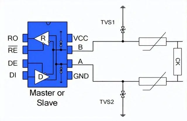
In harsh environments, RS485 communication ports are usually provided with additional protection such as electrostatic protection and lightning surge protection, and even need to be protected against 80V mains power access to avoid damage to smart meters and industrial control hosts. The figure shows three common RS485 bus port protection schemes.
2.1 The first scheme is to connect the TVS devices in parallel to the protective ground at the AB ports, connect the TVS devices in parallel between the AB ports, connect the thermistors in series at the AB ports, and connect the gas discharge tubes in parallel to the protective ground to form a three-level protection scheme;
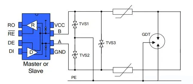
2.2 The second is a three-level protection scheme in which AB is connected in parallel to TVS to ground and in series with thermistor, and a varistor is connected in parallel between AB;
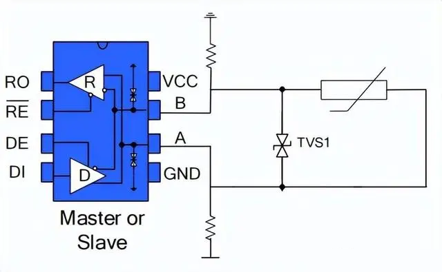
2.3 The third approach involves connecting AB to the power supply and ground through pull-up resistors, with a TVS connected between them. Additionally, one of the ports of A or B is connected to a thermistor.
The working principle of the RS485 interface is mainly based on differential signal transmission. At the transmitting end, the data to be transmitted is converted into differential signals and transmitted to the receiving end through twisted-pair cables. The receiving end converts the received differential signal into a data signal to complete data reception.
The differential signal transmission of the RS485 interface has the following advantages:
RS485 interface supports half-duplex communication, which means that only data transmission or reception can be performed at the same time. Although half-duplex communication reduces the efficiency of data transmission, it simplifies circuit design and reduces costs.
RS485 interface adopts balanced transmission mode, which can reduce the loss during signal transmission and improve the quality of data transmission.
The RS485 interface adopts a bus structure, which can easily achieve data communication between multiple devices.
The RS485 interface can support up to 32 devices for simultaneous data communication.
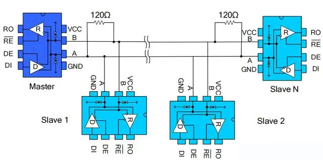
The figure shows a typical network application circuit. These devices can also be used as linear repeaters for cables longer than 4000 feet. To reduce reflections, they should be terminated at both ends of the transmission line with their characteristic impedance. The length of branch connections outside the main line should be as short as possible.
There are two types of signal reflections caused by impedance discontinuity and impedance mismatch during communication:. Impedance discontinuous signal will encounter cable impedance suddenly at the end of transmission line, and even no signal will cause reflection at this place. The method to eliminate this reflection must be to connect a terminal resistor with the same size as the characteristic impedance of the cable at the end of the cable to make the impedance of the cable continuous. Since the transmission of signals on the cable is bidirectional, a terminal resistor of the same size can be connected across the other end of the communication cable. Generally, terminal matching uses the terminal resistor method. The terminal resistance in the RS485 network is set to 120Ω, which is equivalent to the characteristic impedance of the cable, as most twisted-pair cables have a characteristic impedance of approximately 100-120Ω. This matching method is simple and effective, but has a disadvantage that the matching resistor consumes a large amount of power, which is not suitable for systems with strict power consumption restrictions.
RS485 communication can be connected using ordinary twisted-pair cables in general situations. In environments with high requirements, coaxial cables with shielding layers are used for connection. When using the RS485 interface, for a specific transmission line, from the RS485 interface to the maximum cable length allowed for data signal transmission is inversely proportional to the wave frequency of signal transmission. The length data is mainly affected by signal distortion and noise.
During the transmission process, the signal can be amplified by adding relays. Typically, up to nine relays can be added, which means that the maximum transmission distance of RS485 can theoretically reach 9.6km. When long-distance transmission is required, optical fiber can be used as the transmission medium, and an optoelectronic converter can be added at both the transmitting and receiving ends. The transmission distance of multimode optical fiber can reach 5-10km, and if single-mode optical fiber is used for transmission, the transmission distance can reach 50km.
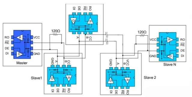
Also known as the daisy chain topology, it is the standard and specification for RS485 bus wiring, and is the recommended RS485 bus topology by organizations such as TIA. The wiring method is to form a hand-in-hand connection between the master control device and multiple slave control devices, such as
As shown in the figure, leaving no branches is the way of hand in hand. This wiring method has the advantages of low signal reflection and high communication success rate. At present, many applications basically adopt this networking mode.
RS485 interface is widely used in various fields such as industrial automation, intelligent transportation, and intelligent buildings. Here are some typical applications:
1. Industrial automation: RS485 interface has been widely used in the field of industrial automation, such as data communication between sensors, controllers, and actuators.
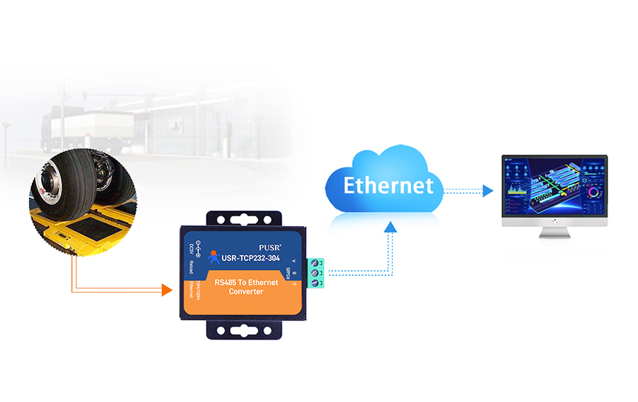
2. Intelligent transportation: RS485 interface has been widely used in the field of intelligent transportation, such as traffic signal control, electronic police, intelligent parking, etc.
3. Intelligent building: RS485 interface has been widely used in the field of intelligent building, such as building automation, security system, access control system, etc.
When using the RS485 interface, you may encounter the following problems. Here are some common problems and solutions:
If there is a communication failure, first check whether the hardware connection is correct, such as whether the cable is connected properly and whether the terminal resistance is set correctly. Secondly, check whether the device parameter settings are correct, such as baud rate, data bits, stop bits, etc.
If the transmission distance is insufficient, try adding repeaters or switches to extend the transmission distance.
If electromagnetic interference is encountered, try using shielded twisted-pair cables or optical fiber transmission to solve the problem.
If there are any device compatibility issues, you can try updating the device driver or firmware, or replacing the device.
RS485 vs. Ethernet: Which is the most commonly used in the industry