Difference between New version and Old version of Ethernet module USR-K6 and USR-K7
1. Functions are totally compatible
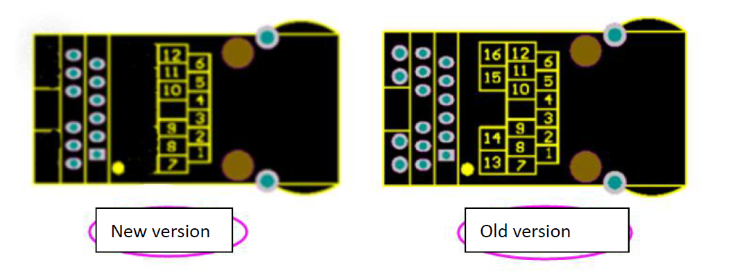
New version: USR-K7, USR-K6
Old version: USR-K3, USR-K2
2. Main differences:
1 Appearance difference: as below pictures.
2 Size: New version is 2mm longer than old verion.
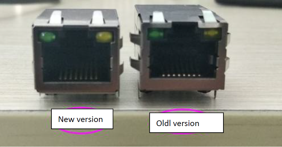
3 New version USR-K7 (Can replace USR-K3) deletes the Network interface indicator
light pins. Other pins are compatible with original ones.
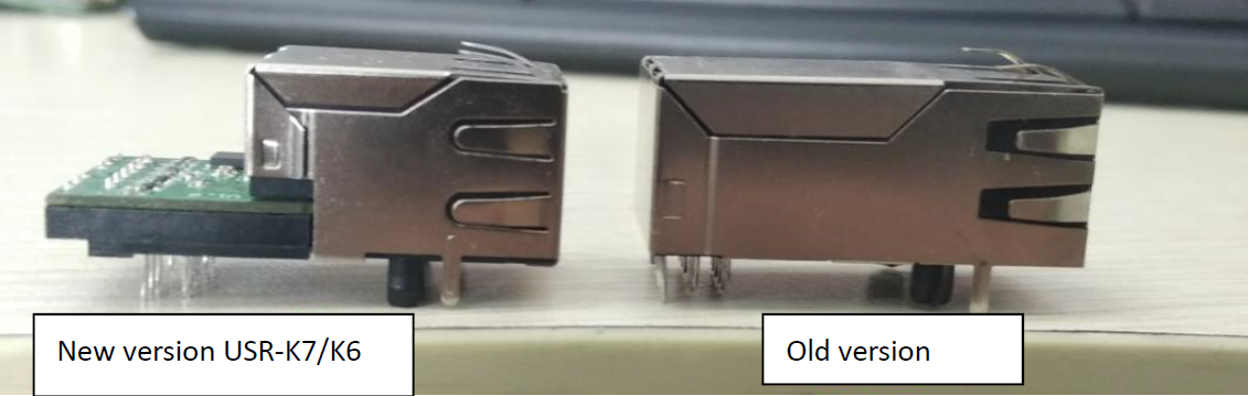
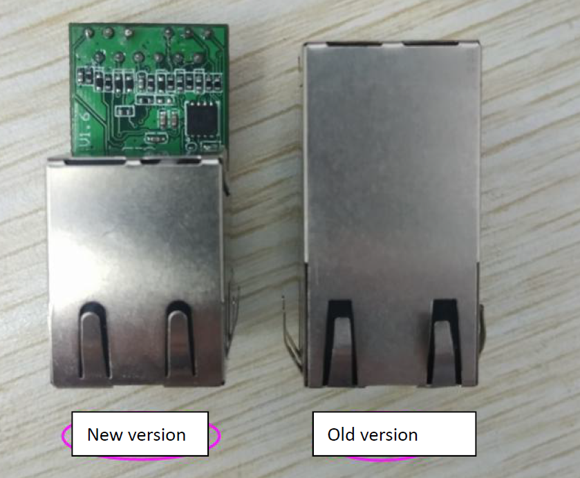
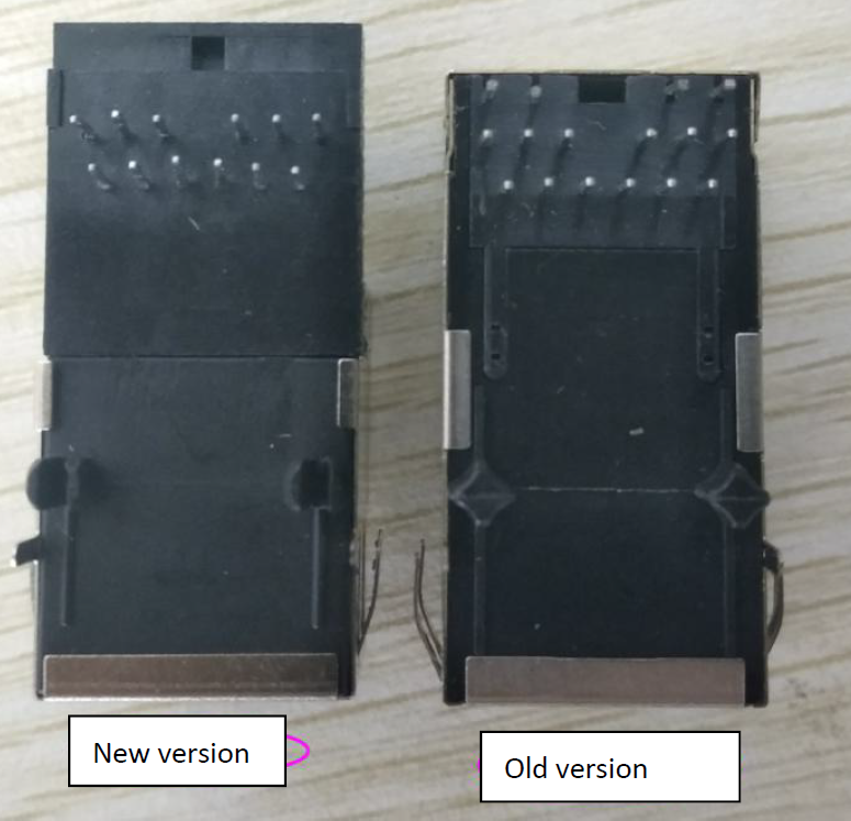
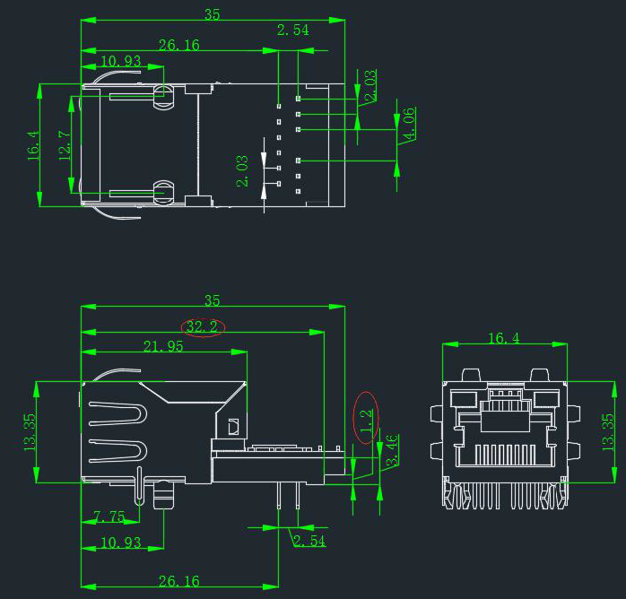
3. Appearance and size comparison
Side view:
Top view:
Front view:
Bottom view:
2mm longer than old ones,
New version K7/K6 hardware design drawing:
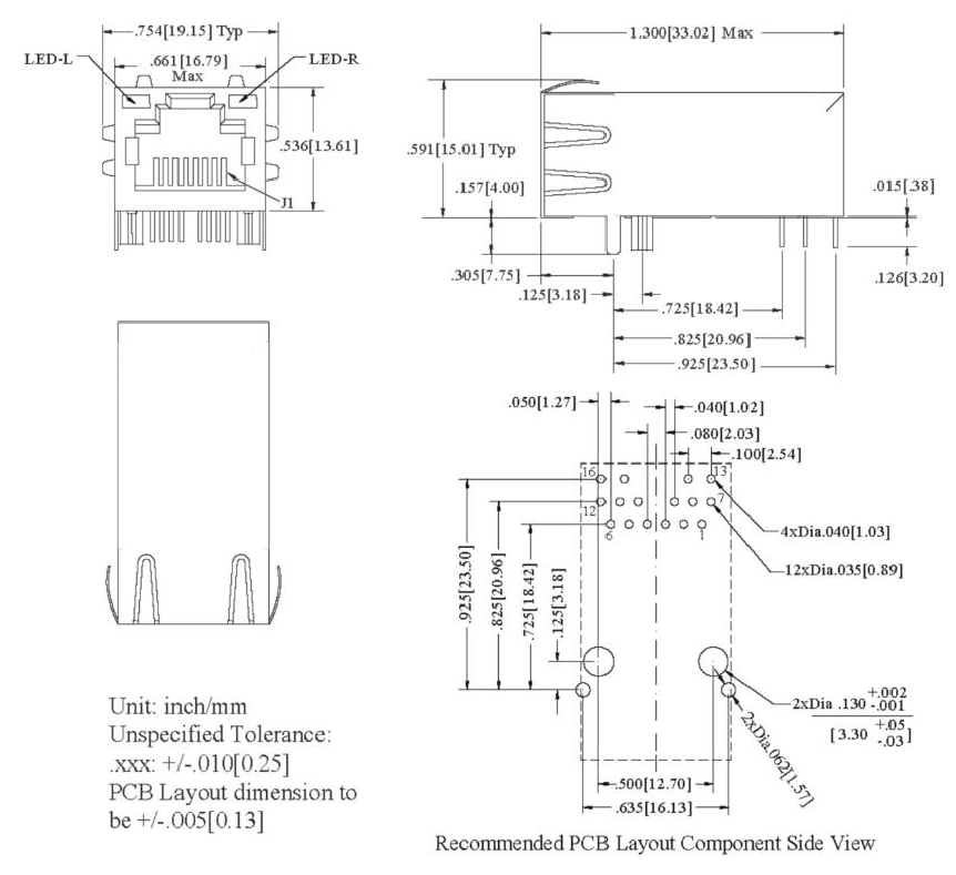
Old version K3/K2 hardware design drawing:
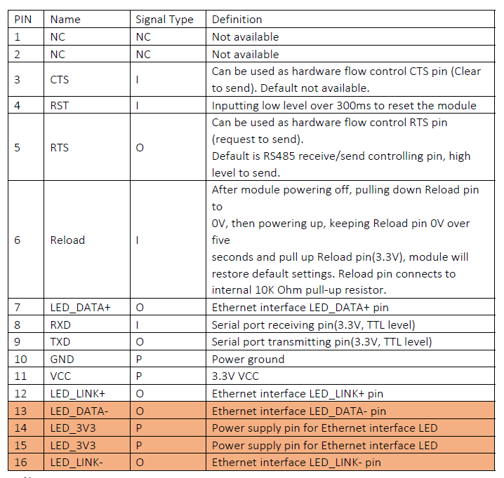
4. Hardware pins comparison
Note: New version K7 deletes the pin 13, 14, 15, 16 ---the external power supply pins. It use internal power supply for the network indicator lights.
Note:
New version Old version
P indicates power pin
I indicates input pin
O indicate output pin
I/O indicate input and output pin
About LED1 abd LED2, the module has add 1K resistor internally, so customer don’t need to add extra current limiting resistor.
Pin 7 and pin 12 both are Microcontroller signal foot lead
Pin 13 and pin 16 are negative pole of LED.