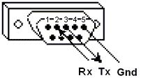
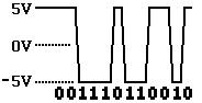
Modbus transfers data through several wires between devices, where the simplest setting is to connect the master and the slave with a serial cable. Data are transferred as a string of 0 or 1, and a digit is a bit. 0 represents a positive voltage while 1 is a negative voltage. The bit data transmission speed is very fast, and the common transmission speed is 9600 baud (i.e. 9600 bits/s).
The information is stored in four different tables in the slave. Two tables store digital quantities, called coils; another two tables store analog quantities, called registers. As for the coil and the register, one can be read only while the other one can be read and written. Each table can store 9999 values. The coil is in one bit and the address are from 0000 to 270E; the register is in one word (16 bits, 2 bytes) and the address are also from 0000 to 270E.
|
Coil/Register Numbers |
Data Addresses |
Type |
Table Name |
|
1-9999 |
0000 to 270E |
Read-Write |
Discrete Output Coils |
|
10001-19999 |
0000 to 270E |
Read-Only |
Discrete Input Contacts |
|
30001-39999 |
0000 to 270E |
Read-Only |
Analog Input Registers |
|
40001-49999 |
0000 to 270E |
Read-Write |
Analog Output Holding Registers |
The number of Coil/Register can be regarded as the name of the address, and they do not appear in the actual sent message. Data Address are in the actual sent message.
For example, the number of the first Holding Register is 40001, and its data address is 0000. The difference between these two numbers is because of the offset.
In the network, each slave is assigned a unique device address, which ranges from 1 to 247. When the master requests data, the first byte of the sent message is the slave address. In this way, after receiving the first byte, the slave will know whether it needs to ignore the subsequent information.
The second byte sent by the master is the function code. This function code tells the slave which table needs to be accessed, whether to write data to the table or read data from the table.
|
Fun Code |
Action |
Table Name |
|
01(01 hex) |
Read |
Discrete Output Coils |
|
05(05 hex) |
Write single |
Discrete Output Coil |
|
15(0F hex) |
Write multiple |
Discrete Output Coils |
|
02(02 hex) |
Read |
Discrete Input Contacts |
|
04(04 hex) |
Read |
Analog Input Registers |
|
03(03 hex) |
Read |
Analog Output Holding Registers |
|
06(06 hex) |
Write single |
Analog Output Holding Register |
|
16(10 hex) |
Write multiple |
Analog Output Holding Registers |
CRC stands for Cyclic Redundancy check, which is adding two bytes after each message sent to check whether there is an error in sending or receiving. Each byte of the message is used to calculate the CRC. The receiver calculates the CRC while receiving the data. And then, it compares the calculation result with the CRC calculated by the sender. If the two are different, an error occurs.
|
Data Addresses |
Read |
Write Single |
Write Multiple |
|
Discrete Output Coils 0xxxx |
FC01 |
FC05 |
FC15 |
|
Discrete Input Contacts 1xxxx |
FC02 |
NA |
NA |
|
Analog Input Registers 3xxxx |
FC04 |
NA |
NA |
|
Analog Output Holding Registers 4xxxx |
FC03 |
FC06 |
FC16 |
Note: FC stands for Function Code
Data request:
11 01 0013 0025 0E84
11: Slave address (0x11 = 17)
01: Function code 01 (Read coil status)
0013: First address of coil (0x0013=19, +1 Offset=#20 coil)
0025: Number of coils to be read (0x25 = 37, 20~56)
0E84: CRC
Data Response
11 01 05 CD6BB20E1B 45E6
11: Slave address (0x11 = 17)
01: Function code 01 (Read coil status)
05: Number of bytes after (37/8=5 bytes)
CD: Coil 27-20 (1100 1101)
6B: Coil 35-28 (0110 1011)
B2: Coil 43-36 (1011 0010)
0E: Coil 51-44 (0000 1110)
1B: 3 spaces and coils 56-52 (0001 1011)
45E6: CRC