This FAQ explains what is the difference between New version and Old version of USR' serial to Ethernet modules. USR' serial to Ethernet modules include USR-K6, USR-K7, USR-K3 and USR-K2.
New version: USR-K7, USR-K6
Old version: USR-K3, USR-K2
K3 and K7: the firmware and functions are fully compatible. K7 adds hardware watchdog for more reliability;
K2 and K6: changed from TI to ST solution, the firmware is not compatible, the function is compatible
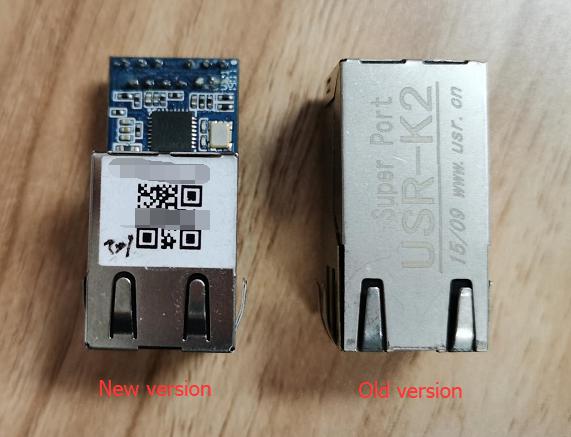
 Appearance difference: As below pictures.
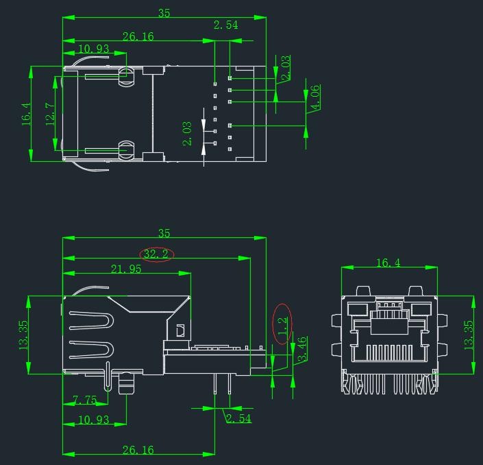
Size: New version is 2mm longer than old verion.
Pins: New version USR-K7 /K6 delete the Network interface indicator light pins. Other pins are compatible with original ones.

Top view:

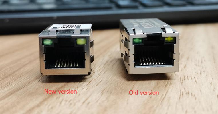
Front view:

Bottom view:
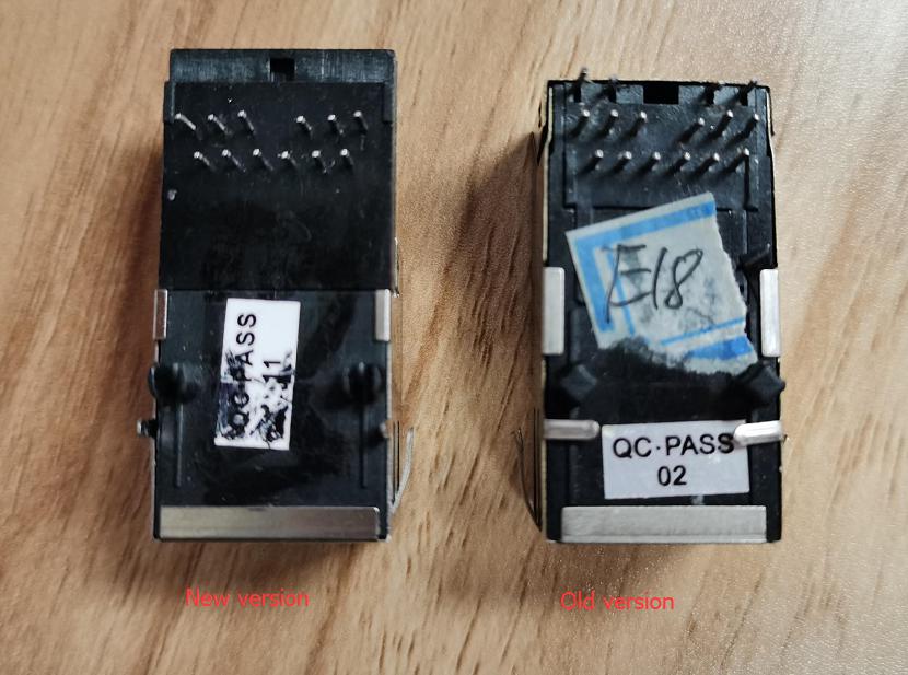

2mm longer than old ones
New version K7/K6 hardware design drawing:
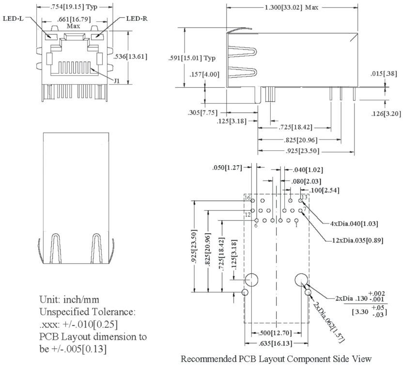
Old version K3/K2 hardware design drawing:
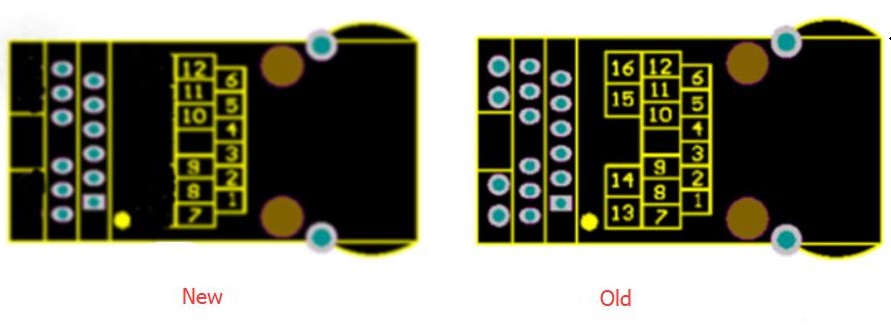
Note: New version K6/K7 deletes the pin 13, 14, 15, 16 ---the external power supply pins. It use internal power supply for the network indicator lights.
|
PIN |
Name |
Signal Type |
Definition |
|
1 |
NC |
NC |
Not available |
|
2 |
NC |
NC |
Not available |
|
3 |
CTS |
I |
Can be used as hardware flow control CTS pin (Clear to send). Default not available. |
|
4 |
RST |
I |
Inputting low level over 300ms to reset the module |
|
5 |
RTS |
O |
Can be used as hardware flow control RTS pin (request to send). Default is RS485 receive/send controlling pin, high level to send. |
|
6 |
Reload |
I |
After module powering off, pulling down Reload pin to 0V, then powering up, keeping Reload pin 0V over five seconds and pull up Reload pin(3.3V), module will restore default settings. Reload pin connects to internal 10K Ohm pull-up resistor. |
|
7 |
LED_DATA+ |
O |
Ethernet interface LED_DATA+ pin |
|
8 |
RXD |
I |
Serial port receiving pin(3.3V, TTL level) |
|
9 |
TXD |
O |
Serial port transmitting pin(3.3V, TTL level) |
|
10 |
GND |
P |
Power ground |
|
11 |
VCC |
P |
3.3V VCC |
|
12 |
LED_LINK+ |
O |
Ethernet interface LED_LINK+ pin |
|
13 |
LED_DATA- |
O |
Ethernet interface LED_DATA- pin (New K6 / K7 delete this pin) |
|
14 |
LED_3V3 |
P |
Power supply pin for Ethernet interface LED (New K6 / K7 delete this pin) |
|
15 |
LED_3V3 |
P |
Power supply pin for Ethernet interface LED (New K6 / K7 delete this pin) |
|
16 |
LED_LINK- |
O |
Ethernet interface LED_LINK- pin (New K6 / K7 delete this pin) |
/ Indicates that the pin is not open yet
P indicates power pin I indicates input pin O indicate output pin
I/O indicate input and output pin
About LED1 and LED2, the module has add 1K resistor internally, so customer don’t need to add extra current limiting resistor.
Pin 7 and pin 12 both are Microcontroller signal foot lead
Pin 13 and pin 16 are negative pole of LED.