Detailed Explanation of AT Command Set for Serial to Ethernet Adapters: A Guide to Custom Message Formats and Trigger Rule Settings
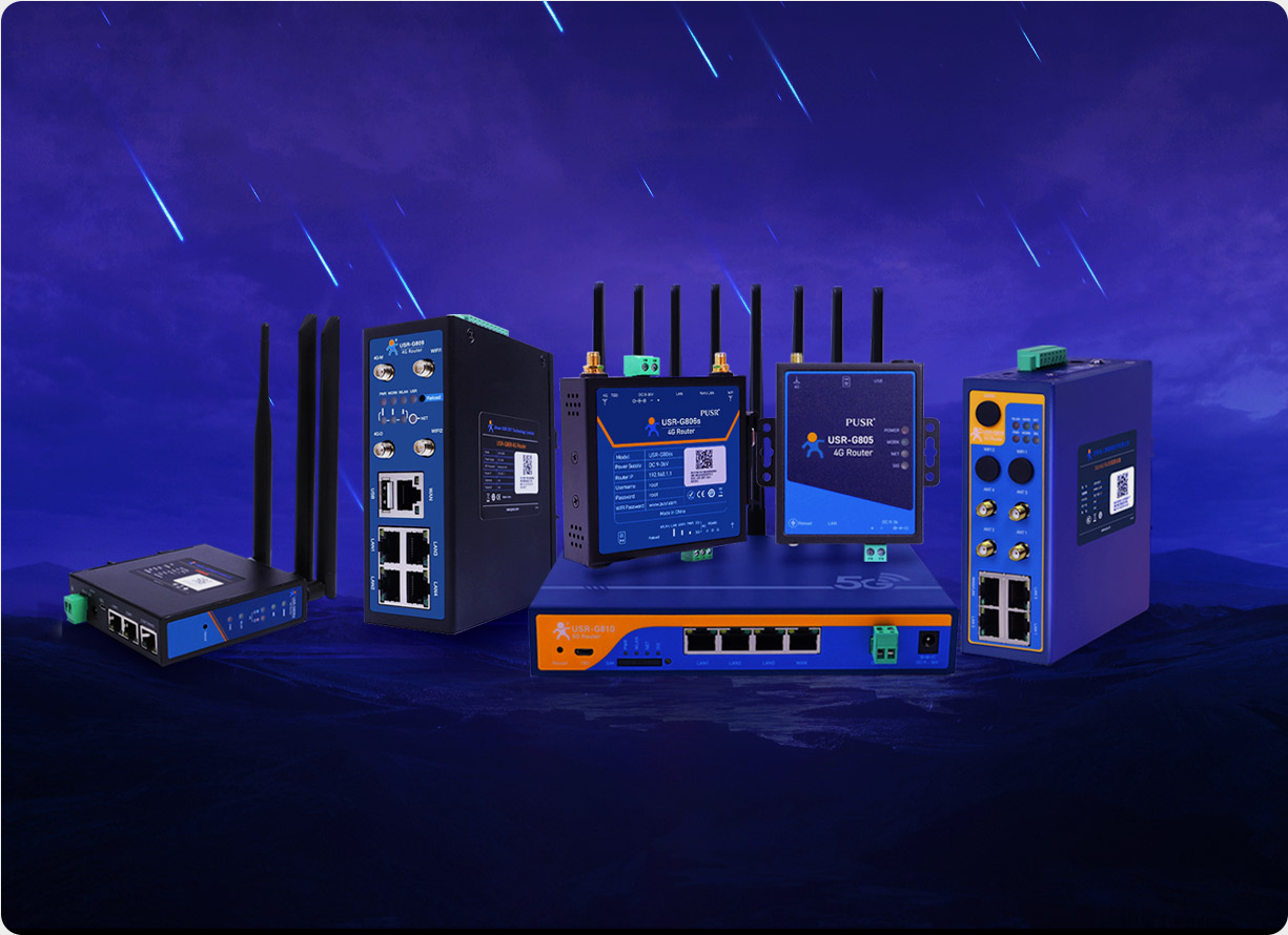
In industrial IoT scenarios, serial to Ethernet adapter serve as the core hub connecting traditional serial devices to Ethernet networks, with their communication protocol flexibility and stability directly impacting data transmission efficiency. However, traditional serial to Ethernet adapter often face three major pain points: rigid message formats leading to poor compatibility, single trigger rules unable to meet complex scenario requirements, and a debugging process that relies on professional tools and is time-consuming and labor-intensive. This article will take the USR-N520 dual serial to Ethernet adapter as an example to provide an in-depth analysis of how to achieve custom message formats and trigger rules through the AT command set, helping enterprises break through technical bottlenecks and improve system integration efficiency.
In a smart factory case, a customer needed to connect 200 truck scale instruments of different brands (supporting the Modbus RTU protocol) to a cloud platform. Traditional serial to Ethernet adapters only supported fixed frame header and frame tail formats, causing some instruments to be unable to parse data due to mismatched check bits. Eventually, an additional protocol conversion module had to be developed, increasing hardware costs by 30%.
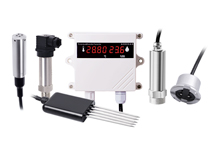
A logistics and warehousing project required sensor data to immediately trigger an alarm when the temperature exceeded limits or the device went offline. However, traditional devices only supported timed polling mode, resulting in an alarm delay of up to 15 minutes and causing cargo losses. Such scenarios urgently need an event-based dynamic response mechanism.
During the deployment of an energy monitoring system, engineers had to carry equipment such as oscilloscopes and logic analyzers to the site for debugging, with a single maintenance session taking more than 4 hours. If remote parameter configuration could be achieved through AT commands, operational and maintenance costs could be significantly reduced.
As an industrial-grade dual serial to Ethernet adapter, the USR-N520 is equipped with a Cortex-M7 core running at 400MHz and supports independent operation of dual serial ports. It features three major technological breakthroughs:
Based on the AT command set of the USR-N520, a message format containing the following elements can be defined:
[Frame Header][Device Address][Command Code][Data Length][Data Field][Check Code][Frame Tail]
Example: When connecting a temperature sensor, design the following format:
0xAA 0x01 0x03 0x02 0x00 0x1A 0x55 0xBB
Send the following commands through a serial debugging tool to complete the configuration:
AT+CUSTOM=1,0xAA,0xBB// Enable custom mode and set the frame header and frame tailAT+ADDR=1// Set the device addressAT+CMD=3,2// Define that command code 0x03 corresponds to 2-byte dataAT+CHECK=CRC16// Enable CRC16 checkIn a smart agriculture project, the linkage between a soil moisture sensor and an irrigation system is achieved through custom messages:
[0xAA][0x02][0x04][0x01][0x32][0x55][0xBB]
When the data field value 0x32 (50% humidity) is below the threshold, the system automatically triggers an irrigation command.
Set data thresholds to trigger alarms through AT commands:
AT+TRIGGER=1,GT,30,1// Channel 1, trigger when greater than 30℃, alarm type 1AT+TRIGGER=2,LT,10,2// Channel 2, trigger when less than 10℃, alarm type 2Application case: A cold chain logistics enterprise achieved real-time monitoring of drug transportation temperatures through this mode, increasing the alarm accuracy rate to 99.2%.
Set data collection and reporting every 5 minutes:
AT+TIMER=1,300,1// Channel 1, 300-second cycle, reporting mode 1Advantage: Compared to traditional polling mode, network bandwidth usage is reduced by 75%.
Maintain device online status detection:
AT+HEARTBEAT=1,60// Channel 1, 60-second heartbeat intervalTechnical principle: If no heartbeat packet is received within 60 seconds, the system automatically marks the device as offline and sends an alert.
Achieve batch configuration of parameters for 20 devices through a Python script:
python
importserialimporttimedefconfig_device(port,addr):ser=serial.Serial(port,115200,timeout=1)commands=["AT+CUSTOM=1,0xAA,0xBB\r\n",f"AT+ADDR={addr}\r\n","AT+CHECK=CRC16\r\n"]forcmdincommands:ser.write(cmd.encode())time.sleep(0.1)response=ser.readline().decode().strip()ifresponse!="OK":print(f"Device{addr}config failed")ser.close()foriinrange(1,21):config_device("COM3",i)An automobile manufacturing enterprise achieved the following through the USR-N520:
After adopting this solution, an environmental monitoring station achieved the following:
Through in-depth customization using the AT command set, the USR-N520 upgrades traditional serial to Ethernet adapters into programmable intelligent communication hubs. According to actual test data from a customer, after adopting this solution, the system integration cycle was shortened by 40%, and data transmission stability was increased to 99.97%. In the wave of Industry 4.0, this flexibility will become the core competitiveness for enterprises' digital transformation. Consult now to obtain your customized solution!