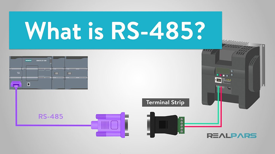
The semi-double network composed of RS485 connection is generally a
two-wire system, and the shielded twisted-pair transmission is adopted. This
wiring type is a bus-type topology structure, and 32 nodes can be connected at
most on the same bus.We know that the initial data is a simple process of analog
signal output, and then the instrument is connected to RS232, which can achieve
point-to-point communication, but this type can not achieve the function of
connection, and then RS485 solves this problem. For this reason, the RS485
connection is introduced in detail in the form of questions and answers.
What is RS485 connection? What are the characteristics of its RS-232-C
connection?
Answer: Due to the early appearance of RS-232-C connection standard, it is
inevitable that there are some differences, mainly including the following four
points:
(1) If the connected signal level is large, it is easy to damage the core
of the connected circuit. Because it is incompatible with the TTL level, it is
necessary to connect the level conversion circuit with the TTL circuit.
(2) The transmission rate is low. In asynchronous transmission, the baud
rate is 20 Kbps.
(3) connecting a signal line and a signal return line to form a
common-ground transmission form, wherein the common-ground transmission is easy
to generate common-mode interference, so that the anti-noise interference
performance is weak.
(4) The transmission distance is limited. The standard value of the maximum
transmission distance is 50 feet. In fact, it can only be around 50 feet. For
RS-232-C, some new standards are constantly emerging. RS-485 is one of them. It
has the following characteristics:
1) Electrical characteristics of RS-485: the voltage difference between two
lines is + (2-6) V for logic "1" and- (2-6) V for logic "0". When the signal
level RS-232-C is reduced, it is not easy to damage the core of the circuit, and
the level is compatible with the TTL level, so it can be connected with the TTL
circuit.
2) The maximum data transmission rate of RS485 is 10 Mbps
3) RS485 is a combination of balanced driver and differential receiver,
which enhances the common mode immunity, that is, it has good noise
immunity.
4) The standard value of the maximum transmission distance of the RS-485
connection is 4000 feet, which can actually reach 3000 to 3000. In addition, the
RS-232-C connection is only allowed to connect one transceiver on the bus, that
is, a single station can be connected. RS-485 on the bus allows up to 128
transceivers to be connected. That is to say, it has multi-station function, so
that users can easily build equipment network with single RS-485 connection.
5) RS485 connection has the advantages of good noise immunity, long
transmission distance and multi-station capability, which makes it an optional
serial connection. Because the semi-double network composed of RS485 connection
generally only needs a root connection, the RS485 connection adopts shielded
twisted pair transmission.The RS485 connector adopts the 9-core socket of DB-9,
the intelligent terminal RS485 connector adopts DB-9 (hole), and the keyboard
connected with the keyboard adopts DB-9 (pin).
RS422, and RS485 concatenation standard
1. Balanced transmission
RS422, RS485, and RS232 are different. The data signal is transmitted
differentially, also known as balanced transmission. It uses a pair of twisted
pairs, with the middle line defined as A and the other line defined as B.
In general, the positive level between the sending driver A and B is + 2 ~
+ 6V, which is a logic state, and the negative level is -2 ~ 6V, which is
another logic state. There is another signal ground C, and there is also an
"enable" terminal in RS-485, which is not possible in RS-422. The "enable"
terminal is used to control the disconnection and connection of the transmission
driver and the transmission line. When "make"
When enabled, the transmit driver is in the blocking state, referred to as
the "third state", that is, it is the third state different from the logic "1"
and "0".
The receiver is also specified relative to the transmitting end. The
receiving and transmitting ends connect AA and BB correspondingly through a
balanced twisted pair. When there is a level of + 200 mV between the receiving
ends AB, a positive logic level is output, and when there is a level of -200 mV,
a negative logic level is output. The level range on the receiver receive
balance line is typically between 200 mV and 200mV6V.
2. RS422 electrical regulations
The full name of the RS-422 standard is "Electrical Characteristics of
Balanced Voltage Digital Circuits", which defines the characteristics of the
circuit. Figure 2 is a typical RS-422 quad. In fact, there is a signal ground
wire, a total of five wires. Figure 1 is its DB9 connector pin definition.Due to
the stronger drive energy of the receiver acquisition impedance and the transmit
driver RS232, it allows multiple receive nodes to be connected on the same
transmission line, up to 10 nodes. That is, a master device (Master), and the
rest are slave devices (Salve). The slave devices cannot communicate with each
other, so RS-422 422 supports point-to-many two-way communication.The input
impedance of the receiver is 4K, so the maximum load at the transmitting end is
10 × 4K + 100Ω (terminating resistance). Since the RS-422 four-wire connection
uses separate transmit and receive channels, it is not necessary to control the
data direction, and any necessary signal exchange between the devices can be
realized in software (XON/XOFF) or hardware (for separate twisted pairs).RS-422
has a maximum transmission distance of 4000 feet (about 1219 1219) and a maximum
transmission rate of 10 Mb/s. The length of the balanced twisted pair is
inversely related to the transmission rate, and the maximum transmission
distance can be achieved only when the transmission rate is below 100kb/s. The
maximum transmission rate can be obtained only at a very short distance.
Generally, the maximum transmission rate that can be obtained on 100-100 long
twisted pair is only 1Mb/s.
RS-422 requires a terminating resistor that is approximately equal to the
characteristic impedance of the transmission cable. The terminal resistance is
not needed in the transmission of moment distance, that is to say, the terminal
resistance is not needed below 300. The terminating resistor is connected to the
farthest end of the transmission cable.
3. RS485 electrical provisions
Because RS-485 was developed from RS422, many of its electrical
specifications are similar to those of RS422. For example, they all adopt the
balanced transmission type and need to connect the terminal resistor on the
transmission line. RS-485 can adopt wire and four-wire type, and the wire system
can realize true multi-point two-way communication.
When using four-wire connection, it can only realize point-to-multipoint
communication with RS422, that is, there can only be one Master device, and
the rest are slave devices. However, it has improved RS422, and 32 more devices
can be connected to the four-wire or wire-connected bus.
The difference between RS-485 and RS422 is that their common-mode output
voltages are different. RS485 is between -7 V and 7V + 12 V, while RS-422 is
between -7 V and 7V + 7 V. The maximum input impedance of RS485 receiver is 12K, and RS422 is 4K; The old Gorge Top Transport RS485 fulfills all RS422
specifications, so RS-485 drivers can be applied in the RS422 network.
RS485 is similar to RS422 422, its maximum transmission distance is about
1219 1219, and its maximum transmission rate is 10 Mb/s. The length of the
balanced twisted pair is inversely related to the transmission rate, and it is
only possible to specify the longest cable length at a rate below 100 kb/s. The
maximum transmission rate can be obtained only at a very short distance.
Generally, the maximum transmission rate of 100/100 long twisted pair is only
1Mb/s.
RS485 requires 2 terminating resistors equal to the characteristic
impedance of the transmission cable. The terminal resistance is not needed in
the transmission of moment distance, that is to say, the terminal resistance is
not needed below 300. Terminating resistors are connected at both ends of the
transmission bus.
III. Precautions for RS-422 and RS485 network installation
RS422 can hold 10 nodes, and RS485 485 can hold 32 nodes, so multiple
nodes form a network. The network topology generally adopts a terminal-matched
bus structure and does not support a ring or star network. When building a
network, the following points should be noted:
1、A twisted-pair cable is used as the bus to connect the nodes in series.
The length of the outgoing line from the bus to each node should be as short as
possible, so as to minimize the impact of the reflected signal in the outgoing
line on the bus signal. Some wrong connection formulas (a, C, e) and correct
connection formulas (B, d, f) are common in actual application.Although the
connections of a, C and e are incorrect, they may still work normally in short
distance and low speed. However, with the extension of communication distance or
the increase of communication speed, the adverse effects will become more and
more serious. The main reason is that the signal will be superimposed with the
original signal after being reflected at the end of each channel, which will
cause the signal quality to decline.
2. Attention should be paid to the continuity of the characteristic
impedance of the bus, and the signal will be reflected at the point of impedance
discontinuity. This discontinuity is prone to occur when different cables are
used in different sections of the bus, or when too many transceivers are
installed close together on a section of the bus, or when too long a branch is
brought out of the bus.
In general, a single, continuous signal channel shall be provided as a
bus.
IV. Description of Matching on RS422 and RS485 Transmission Lines
For RS422 and RS485 buses, the terminating resistors should be matched.
But that terminal match may not be considered at short distance and low rate. So
under what circumstances do we not consider matching? In theory, at the midpoint
of each received data signal, the match can be disregarded as long as the
reflected signal is sufficiently attenuated at the beginning of the sampling.But
this is difficult to grasp in practice. MAXIM Company in the United States has a
chapter that mentions an empirical principle to determine what data rate and
cable length need to be matched: when the signal transition time (rise or fall
time) exceeds three times the time required for the electrical signal to travel
along the bus in one direction, it can not be matched.For example, the rise or
fall time of the output signal of RS-485 with slope-limited characteristics
connected to MAX483 is up to 250 ns, and the signal transmission rate on a
typical twisted pair is about 0.2m/ns (24 AWGPVC cable), so as long as the data
rate is within 250 kb/s and the cable length is not more than 1616, When MAX483
is used as RS-485 connection, there is no need to add terminal matching.
Generally, the terminal matching adopts the terminating resistor method. As
mentioned above, RS422 shunts the resistor at the far end of the bus cable,
while RS485 shunts the resistor at the beginning and end of the bus cable. The
terminating resistor is generally taken as 100 Ω in RS422 and 120 Ω in
RS485.Resistance equivalent to the characteristic impedance of the cable,
since most twisted-pair cables have a characteristic impedance of about 100 to
120 Ω. This matching method is simple and effective, but it has a disadvantage
that the matching resistor consumes more power and is not suitable for systems
with strict power consumption limits.
Another more power-saving matching type is RC matching, which can save part
of the power by cutting off the DC component of the capacitor C. However, the
value of capacitor C is a difficult problem, which requires a compromise between
power consumption and matching quality.
There is also a matching method of the collector, which does not achieve
real "matching", but it can quickly weaken the reflected signal by clamping the
collector, so as to improve the signal quality. And that energy-saving effect is
remarkable.
V. Grounding of RS422 and RS485
Electrical system grounding is important but often overlooked. Improper
grounding treatment often leads to unstable operation of the electrical system
and even endangers the safety of the system.The grounding of RS-422 and RS-485
transmission network is also very important, because the unreasonable grounding
system will affect the stability of the whole network, especially in the case of
harsh working environment and long transmission distance, the requirements for
grounding are more stringent. Otherwise, the damage rate is lower.In many cases,
RS422 and RS485 communication links are simply connected to each other through
twisted pair.
Connect the "A" and "B" ends of. Ignoring the connection of signal ground,
this connection method can be done normally in many cases, but it buries a lot
of hidden dangers, which has the following reasons:
1、Common-mode interference problem: As mentioned above, RS-422 and RS-485
are both used to transmit signals in differential mode, and do not need to
detect signals relative to a reference point. The system only needs to detect
the potential difference between the two lines.However, they tend to ignore the
fixed common-mode voltage range of the transceiver. For example, the common-mode
voltage range of the RS-422 transceiver is -7 ~ + 7 V, and that of the RS-485
transceiver is -7 ~ + 12 V. Only when the above conditions are met, can the
whole network operate normally. When the common mode voltage of the network line
exceeds this range, it will affect the stability and reliability of
communication, and even damage the connection.Taking fig. 1 as an example, when
the transmit driver A transmits data to the receiver B, the output common-mode
voltage of the transmit driver A is VOS, and since the two systems have their
own ground systems, there is a ground potential difference VGPD. The common-mode
voltage at the receiver input, VCM, then reaches VCM = VOS + VGPD.RS-422 and
RS-485 standards both specify VOS ≤ 3 V, but VGPD may have a large amplitude
(volts or even several volts), and may be accompanied by strong interference
signals, causing the receiver common-mode input VCM to exceed the normal range,
and generating interference current on the transmission line, which can affect
normal communication or damage the communication circuit.
2. (EMI) problem: The common-mode part of the output signal of the
transmission driver needs a return path. If there is no low-resistance return
path (signal ground), it will return to the source end in the form of radiation,
and the whole bus will radiate electromagnetic waves outward like a giant
antenna.
Because of the above reasons, although RS422 and RS485 adopt differential
balanced transmission, there must be a low-resistance signal ground for the
whole RS-422 or RS-485 485 network. A low resistance signal ground connects the
two grounded circuits together so that the common-mode interference voltage VGPD
is short-circuited.
This signal ground can be an extra wire (shielded twisted pair) or the
shield of a shielded twisted pair. This is the most common grounding method.
It is worth noting that this approach is only effective for resistive
common mode interference, because the internal resistance of the interference
source will not form a very large ground loop current after short circuit, which
will not have a great impact on communication. When the internal resistance of
the common-mode interference source is low, it will form a large loop current on
the ground line, affecting normal communication. The author believes that the
following three measures can be taken:
(1) If the internal resistance of the disturbance source is not constant, a
current-limiting resistor can be added to the ground line to limit the
disturbance current. An increase in the resistance to ground may cause the
common-mode voltage to rise, but it will not affect normal communication as long
as it is controlled within an appropriate range.
(2) Float technology is adopted to cut off the grounding loop.This is a
common and effective method. When the internal resistance of common-mode
interference is very high, the above method is no longer effective. At this
time, it can be considered to float the interfering node (such as the field
device in a harsh working environment) (that is, the circuit ground of the
system is isolated from the chassis or ground), so as to cut off the ground loop
and not form a very high loop current.
(3) Adopt isolated connection. In some cases, for safety or other
considerations, the circuit ground must be connected to the chassis or ground
and cannot be suspended. At this time, isolation connection can be used to cut
off the grounding circuit, but there should still be a ground wire to connect
the common terminal of the isolation side with other grounding devices.
VI. Network failure protection of RS422 and RS485
Both the RS422 and RS485 standards specify a receiver threshold of ± 200
mV. This specification provides better noise rejection. As mentioned earlier,
the output is positive logic when the receiver A-level B-level is above + 200
mV, and negative logic when the receiver A-level B-level is above + 200
mV.However, due to the existence of the third state, that is, after the host
sends a message data at the sending end, the bus is placed in the third state,
that is, when the bus is idle, there is no signal to drive the bus, so that the
voltage between AB is between -200 and + 200 mV and tends to 0 V, which brings a
problem: the output state of the receiver is uncertain.If the output of the
receiver is 0 V, the slave device in the network interprets this as a new start
bit and attempts to read the following byte. Since there is never a stop bit, a
frame error result is produced, no more devices request the bus, and the network
is paralyzed.In addition to the situation described above where an idle bus
results in a voltage difference of less than 200 mV between the two wires, this
situation can also occur with an open or short circuit. Therefore, certain
measures should be taken to prevent the receiver from being in an uncertain
state.
Normally, the bias is applied to the bus. When the bus is idle or open, the
bias resistor biases the bus to a definite state (differential voltage ≥ -200
mV). As shown in Figure 1. A is pulled up to ground and B is pulled down to 5 V.
The resistance is typically 1 kΩ and varies with the capacitance of the
cable.
The above method is a classical method, but it still can not solve the
problem of bus short circuit. Some experts can solve this problem by moving the
receiving threshold to -200mV/-50mV.
VII. Transient protection of RS422 and RS485
The signal grounding measures mentioned above are only for the protection
of common mode interference at low frequency, but for the transient interference
at very high frequency. Because the frequency signal of the transmission line is
equivalent to the inductance, the grounding line is actually equivalent to the
open circuit for the frequency transient disturbance.Such transients, though
brief in duration, may be in the hundreds of kilovolts.
In the actual application environment, there is still the possibility of
frequency transient disturbance. In the process of switching power inductive
loads such as motors, transformers, relays, etc. Or lightning, there will be
transient disturbances of large amplitude, which will damage RS422 or RS485
communication connections if not properly protected. This kind of transient
disturbance can be protected by isolation or bypass.
1、Isolation protection method. This scheme actually transfers the transient
voltage to the electrical isolation layer in the isolation connection. Because
of the insulation resistance of the isolation layer, it will not produce harmful
surge current and play a protective role.Frequency transformer, optocoupler and
other components are usually used to achieve electrical isolation. Some device
manufacturers have integrated all these components into the IC, which makes it
very simple. The advantage of this scheme is that it can withstand the transient
disturbance of voltage and duration for a long time, and it is easy to realize,
but the disadvantage is that the cost is low.
2、Bypass protection. This kind of transient suppression element (such as
TVS, MOV, body discharge tube, etc.) bypasses the harmful transient energy to
the ground, which has the advantage of low cost and the disadvantage of limited
protection energy. It can only protect the transient disturbance within a
certain energy, and the duration can not be very long. It also needs a good
channel to connect to the ground, which is difficult to achieve.In practice, the
above two schemes should be combined and operated flexibly, as shown in Figure
1. In this approach, the isolation link isolates the amplitude transient
intrusions, and the bypass element protects the isolation link from breakdown by
excessive transient voltages.
How to consider the length of transmission cable when adopting RS485
connection?
When connecting RS485, for a specific transmission line, the maximum
allowable cable length for data signal transmission from the transmitter to the
load is a function of the data signal rate, and this length data is mainly
limited by signal distortion and noise. The maximum cable length versus signal
rate curve is for a 24 AWG copper twisted pair telephone cable (wire diameter
0.51mm) with a line-to-line bypass capacitance of 52. 5 PF/M at 100 ohms of
terminating load resistance. When the data signal rate is reduced below
90Kbit/S, the cable length is limited to 1200M, assuming that the maximum
allowable signal loss is 6 dBV. In real time it is entirely possible to obtain
its cable length. When cables of different wire diameters are used.The maximum
cable length obtained is not the same.
How to realize RS485/422 multipoint communication
Only transmitters can transmit on the RS-485 bus at any time. Half-double
type, master and slave can only send one. Full duplex, the master station can
always send, and the slave station can only send.
When RS485/RS422 is connected for communication, under what conditions
does the terminal need to be matched? How is the resistance value determined?
How to configure the terminal matching resistor?
In the long line signal transmission, in order to avoid the reflection and
echo of the signal, it is necessary to connect a terminal matching resistor at
the receiving end. Its terminal matching resistance value depends on the
impedance characteristics of the cable and is related to the length of the
cable.
The RS485/RS-422 422 is typically a twisted pair (shielded or screened)
connection, and the termination resistance is typically between 100 and 140
ohms, with a typical value of 120 ohms. In the actual configuration, the two
terminal nodes of the cable, namely the nearest end and the farthest end, are
respectively connected with a terminal resistor, and the node in the middle part
cannot be connected with the terminal resistor, otherwise, a communication error
will occur.
RS485 485 Do not know which is the farthest site, how to connect the
matching resistor?
This situation occurs because the principle that the connection of the site
bus should be as short as possible is not followed when the user composes RS-485
485. If the bus wiring follows this principle, there is no problem of not
knowing which site is the farthest. And be aware that with such wiring, the
system will not do well.
RS485/RS422 Why does the receiver still have data output when
communication is stopped?
After sending data, RS-485/RS-422 requires all the send enable control
signals to be turned off and keep the receive enable active. At this time, the
bus driver is in the blocking state and the receiver can monitor whether there
is new communication data on the bus.However, because the bus is in the source
drive state (if the bus has a terminal matching resistor, the differential level
of line A and line B is 0, the output of the receiver is uncertain, and it is
very sensitive to the change of the differential signal on line AB; if the
terminal matching occurs, the bus is in the impedance state, and the output of
the receiver is uncertain), it is vulnerable to external noise interference.When
the noise voltage exceeds the input signal threshold (typically ± 200mV), the
receiver will output data, causing the corresponding UART to receive valid data,
resulting in an error in the following normal communication. Another situation
may occur at the moment of turning on/off the transmit enable control, causing
the receiver to output a signal, which will also cause the UART to receive
incorrectly.
Solution:
1) On the communication bus, clamp the bus by pulling up the in-phase
output end (line A) and pulling down the reverse-phase output end (line B) to
ensure that the output of the receiver is a fixed "1" level;
2) Replace the circuit with MAX308x series products with built-in fail-safe
mode;
3) Through software elimination, that is, adding 2-5 initial synchronous
bytes in the communication data packet, the real data communication is started
only after the synchronous header is full.
Three factors affecting the communication speed and reliability of RS-485
bus
Signal reflection in communication cables
During communication, there are two types of signals that cause signal
reflections: impedance discontinuities and impedance mismatches. Impedance
discontinuity. When the signal suddenly meets the cable at the end of the
transmission line, the impedance is very small, and the signal will be reflected
at this ground, as shown in Figure 1. The principle of signal reflection is
similar to the reflection of light from one medium into another.To eliminate
this reflection, a terminating resistor of the same characteristic impedance as
the cable must be connected across the end of the cable to make the impedance of
the cable continuous.Because the signal transmission on the cable is
bidirectional, the same terminal resistor can be bridged at the other end of the
communication cable. Theoretically, as long as the terminal resistor matching
the characteristic impedance of the cable is bridged at the end of the
transmission cable, the signal reflection phenomenon will not occur any
more.However, in the implementation, because the characteristic impedance of the
transmission cable is related to the communication baud rate and other
environment, the characteristic impedance can not be exactly equal to the
termination resistance, so more or less signal reflection will still exist.
Another cause of signal reflection is the impedance mismatch between the
data transceiver and the transmission cable. The reflection caused by this
reason is mainly manifested in the data confusion of the whole network when the
communication line is idle.
In the final analysis, the influence of signal reflection on data
transmission is that the reflected signal triggers the comparator at the input
end of the receiver, so that the receiver receives the wrong signal, resulting
in CRC error or error of the whole data frame.