When we are engaged in the development of embedded projects, we often encounter a variety of serial communication problems. According to the previous debugging and development experience, this paper summarizes a serial communication troubleshooting guide, hoping to provide some troubleshooting directions and methods for engineers who often use Serial to Ethernet Device Server.
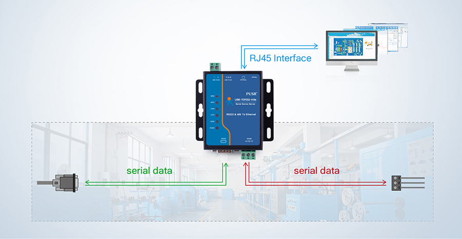
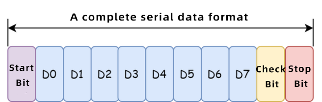
Serial communication is a kind of communication mode that transmits data by bit between peripherals and computers, or between peripherals and peripherals through data signal lines, ground lines, etc. The communication format of this communication mode includes start bit, data bit, check bit and stop bit, as shown in the following figure. Serial communication is characterized by low cost but slow transmission speed.The distance of serial communication can be from several meters to several kilometers.
After a brief introduction to serial communication, let's get down to business. The direction for us to troubleshoot serial communication problems is basically as follows, as shown in the figure.
1. Check the middleware
There must be a sending end and a receiving end in serial communication, and both of them pass through middleware (such as wires). In case of problems, the first thing is to ensure that the wires are connected normally. If this part is not determined and other directions are directly investigated, it is likely to do useless work.
2. Troubleshoot the hardware layer
The logic analyzer, oscilloscope and other instruments are used to judge whether the pin waveforms of the sending end and the receiving end are normal during sending, receiving and idling. When the serial port is idle, it is high level, and there will be level change when there is data. It is also necessary to determine whether the voltage is normal.The position of waveform measurement starts from the end point, and then the detection points in the middle part are checked in turn to determine the location of the problem.
If waveform deformation, distortion, abnormal voltage and other conditions are found, please ask the hardware engineer to assist in troubleshooting. The waveform is visible at its start point, but not at its end point, and a multimeter is required to determine if there is a cold solder joint on the pin.
3. Check the serial driver layer
If there is no problem after checking the hardware, but there is no waveform in the serial port of the sending end, it is necessary to check whether the serial port driver is configured successfully. The Tx and Rx pins at the transmitting end can be short-circuited for loopback test. It is better to test with a simple routine first, and try to eliminate the influence of multiple variables.When troubleshooting, special attention should be paid not only to the logic of the code, but also to the actual debugging, and be good at using the software debugging window to observe the values of the relevant registers.
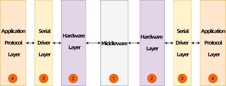
4. Application protocol layer
Through the investigation of the above directions, it can be proved that there is no problem with spontaneous receipt. The next step is to verify whether the two sides can communicate normally. Possible problems at the application protocol layer include:
① There is a problem with the data protocol between the sending end and the receiving end, such as CRC, frame header and trailer check, and parsing of data packets.
② The serial port configuration parameters of the sending end and the receiving end: the baud rate and the check bit are inconsistent, resulting in the failure of communication.
We also need to pay attention to the following points:
① As the signal is easy to be interfered, it is recommended to use a shielded wire, and the wiring must be strict, and it is better to ground if grounding is needed. For some 485 communication, it is also necessary to consider connecting a terminal resistor to match. If it is RS232 communication, try not to make the line too long.
② Because many devices have errors in the baud rate calculated by the external crystal oscillator or internal clock. In this case, if the message is too long, it will lead to the accumulation of errors, and then the serial identification will be garbled or can not be received.
③ In some places where there may be interference, you can consider using odd parity or even parity, so that you can filter out the wrong messages or try to use some data parity protocols to prevent data errors.