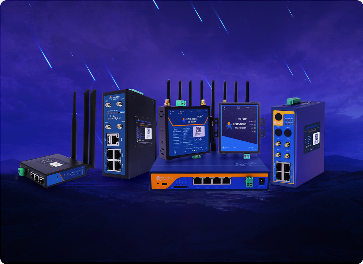
Serial to ethernet converter is actually the industrial level of serial server. Although serial servers are not only used in industrial scenarios, but also in commercial environments such as buildings, security access control, traffic lights and so on. Industrial grade is used in the process of production, and the specific content standard is determined according to the product attributes. Industrial serial servers usually need to reach the working temperature of -40 ℃ -85 ℃ to adapt to the harsh environment of severe cold and heat. Commercial-grade serial servers are usually used at -25 ~ 75 ℃, which is enough for practical scenarios.
The concept of serial communication is very simple. Serial communication refers to a communication mode in which data is transmitted by bit between peripherals and computers through data signal lines, ground lines, control lines, etc. This communication mode uses less data lines and can save communication costs in long-distance communication, but its transmission speed is lower than parallel transmission. It is simple and enables long-distance communication.
Communication is accomplished using 3 wires: (1) ground, (2) transmit, and (3) receive. Because serial communication is asynchronous, a port can send data on one wire while receiving data on another. Other lines are used for handshaking, but are not required.
The most important parameters for serial communication are baud rate, data bits, stop bits, and parity. For two ports to communicate, these parameters must match:
(1) Baud rate: This is a parameter to measure the communication speed. It represents the number of bits transmitted per second. High baud rates are often used for communication between instruments placed in close proximity, a typical example being communication with GPIB devices.
(2) Data bit: This is a parameter that measures the actual data bit in the communication. When the computer sends a packet, the actual data is not 8 bits. The standard values are 5, 7, and 8 bits. Since the actual data bits depend on the choice of communication protocol, the term "packet" refers to any instance of communication.
(3) Stop bit: used to represent the last bit of a single packet. Typical values are 1, 1.5, and 2 bits. The greater the number of bits available for stop bits, the greater the tolerance for different clock synchronizations, but the slower the data transfer rate at the same time.
(4) Parity bit: a simple error detection method in serial communication. There are four types of error detection: even, odd, high, and low. In the case of even and odd parity, the serial port will set the check bit with a value to ensure that the transmitted data has even or odd logic high bits.
What is the function of the serial port?
Serial port (full name serial interface), also known as serial communication interface or serial communication interface (usually referred to as COM interface), is an expansion interface using serial communication mode.
Serial interface means that the data is transmitted bit by bit in sequence. It is characterized by simple communication lines, which can achieve two-way communication as long as a pair of transmission lines (telephone lines can be directly used as transmission lines), thus greatly reducing the cost. It is especially suitable for long-distance communication, but the transmission speed is slow.
RS232 (EIA RS-232) Is one of the serial communication interface standards in common use. It was established by the Electronic Industries Association (EIA) in 1970 in conjunction with the Bell System, modem manufacturers and computer terminal manufacturers. Its full name is "Interface Standard for Serial Binary Data Exchange between Data Terminal Equipment (DTE) and Data Communication Equipment (DCE)". Below small make up to introduce "RS232 serial port definition RS232 serial port wiring diagram and wiring method".
In serial communication, both sides of communication are required to use a standard interface, so that different devices can be easily connected to communicate. RS-232-C interface (also known as EIA RS-232-C) is the most commonly used serial communication interface. The computer serial port (RS232) has 9 pins in total, which are arranged in order. The definition of each pin is as follows:
The wiring diagram of RS232 and UART serial port communication is as follows:
There are two methods for RS232 serial port wiring:
1. Direct connection method: The direct connection method of the RS232 serial port line is the normal connection: 2 to 2, 3 to 3 (that is, the RX at one end is connected to the RX at the other end, and the TX is connected to the TX at the other end) 5 to 5.
2. Cross connection method: The RS232 serial port cable cross connection method is cross connection: 2 to 3, 3 to 2 (that is, the RX at one end is connected to the TX at the other end, and the TX is connected to the RX at the other end) 5 to 5.
Note: Under normal circumstances, the connection between the equipment and the computer for communication requires the direct connection of the RS232 serial port cable; The cross line of RS232 serial port line will be used for communication between equipment and equipment.