In new energy projects such as photovoltaic, wind power, and energy storage, the stable operation of power stations is not only affected by core equipment like inverters and energy storage cabinets. Once auxiliary facilities in step-up stations, centralized control rooms, and communication rooms—including air conditioners, UPS, temperature and humidity sensors, water immersion detectors, and access control systems—malfunction, they may also cause communication interruptions, equipment shutdowns, and even safety risks.
For manufacturers that produce computer room dynamic environment monitoring systems, power distribution monitoring cabinets, or new energy supporting equipment, the difficulty often lies not in "whether sensors are available", but in how to uniformly connect devices from different manufacturers and reliably transmit data to the power monitoring platform.
In a new energy computer room, devices usually come from a wide range of sources.
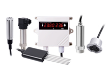
UPS may use RS485 communication, air conditioning controllers adopt Modbus RTU or Modbus TCP; temperature and humidity sensors may be RS485 devices; water immersion detectors, door magnetic sensors, and human body infrared sensors mostly output switch signals; some fans and exhaust equipment also need start-stop control via relays.
Individually, these devices are not complex, but three problems easily arise once the project enters the integration phase.
First, interfaces and protocols are not unified. Different manufacturers have different register addresses, communication parameters, and data formats, making it difficult for the upper-level monitoring platform to directly connect to each device one by one.
Second, there is a protocol gap between on-site devices and the power platform. Bottom-layer devices in computer rooms commonly use interfaces such as Modbus, DI, and AI, while the existing dispatching and monitoring systems of new energy stations may require access in accordance with the IEC 60870-5-101, 104 or IEC 61850 system. If the platform is modified every time a new type of device is added, later maintenance will become increasingly complicated.
Third, many alarms cannot only rely on cloud processing. For example, for scenarios like high temperature in the computer room, water immersion, or UPS abnormality, if the raw data is first uploaded to the server for judgment and control delivery, the local linkage may fail once the intermediate network is interrupted.
Therefore, in actual projects, a more reasonable approach is to add an?IoT gateway device?layer on-site in the computer room.
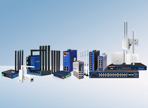
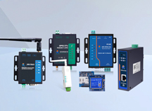
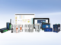
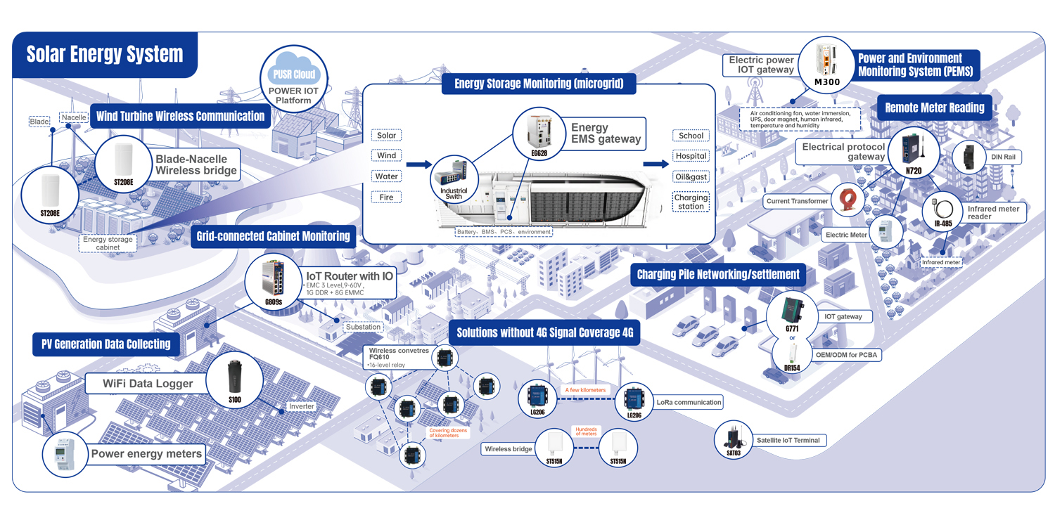
Taking the IoT Gateway Device USR-M300 as an example, it can be placed in the computer room dynamic environment control cabinet as a data aggregation node between on-site devices and the upper-level monitoring system.
The gateway itself provides interfaces such as RS232/RS485, Ethernet, DI, DO, and AI. It can simultaneously collect data from serial port, network, and IO devices, and supports Modbus RTU/TCP conversion, data point collection, logic linkage, and Node-RED graphical development. According to official documents, it can configure up to approximately 2000 data collection points on the edge side.
During actual wiring, devices can be classified by type:
Air conditioners, fans, UPS, and temperature/humidity sensors are connected via RS485 or Ethernet;
Switch signal devices such as water immersion detectors, door magnetic sensors, human body infrared sensors, and smoke detectors are connected to DI;
Fans, sound-light alarms and other equipment that require remote control can be linked via DO or external relays.
In this way, data of various types of devices first forms a unified data point table inside the gateway, and then is output to the upper-level system.
The IoT Gateway Device M300 supports local data judgment and linkage. For example, it can start the fan when the temperature exceeds the set value, or immediately trigger an alarm when a water immersion signal is detected. Such control does not need to fully rely on the cloud. Even if the uplink network is temporarily abnormal, the basic protection logic in the computer room can still be executed on site.
In new energy projects, this step is often more important than hardware wiring.
A relatively reliable approach is not to make all bottom-layer devices directly support IEC 101, 104 or 61850. Instead, first uniformly collect data from on-site devices to the edge gateway, and then establish a standard data point table, for example:
Temperature, humidity, UPS status, air conditioner operation status, water immersion alarm, door magnetic status, human body infrared alarm, etc.
After that, map these data to the point tables of IEC 101, 104 or 61850 according to the requirements of the upper-level system.
Special attention should be paid: The main protocol capabilities clearly listed in the public product documents of the IoT Gateway Device USR-M300 include Modbus RTU/TCP, MQTT, TCP, OPC-UA Server, etc., and it supports Node-RED and secondary development.
Therefore, if the project explicitly requires the IoT Gateway Device M300 to directly undertake IEC 101/104/61850 protocol conversion, it is necessary to confirm whether the corresponding firmware, Node-RED extended program or secondary development solution has been adapted during the project selection phase. Do not assume that it supports these protocols by default just because of the name "IoT gateway device".
For power projects with strict requirements, you can also adopt the mode of "IoT Gateway Device M300 is responsible for collection and edge processing + power protocol program is responsible for 101/104/61850 conversion" to separate the device collection layer and the power communication layer.
During on-site implementation, it is recommended to first make the device list and point table, instead of installing the gateway first.
First, list all devices in the computer room, including air conditioners, UPS, temperature and humidity sensors, water immersion detectors, door magnetic sensors, and human body infrared sensors, and confirm their communication interfaces, protocols, station numbers, baud rates, and the data to be collected.
The second step is to plan RS485 buses, Ethernet, and DI/DO wiring according to device types, so as to avoid continuously adding conversion modules in the later stage.
The third step is to complete device data collection in the IoT Gateway Device M300, and establish unified variable names, such as "Computer Room Temperature", "UPS Fault", "No.1 Air Conditioner Operation", "Water Immersion Alarm".
The fourth step is to configure edge logic, and complete events that require rapid on-site response locally, such as starting the fan at high temperature and triggering a sound-light alarm for water immersion.
Finally, complete the 101, 104 or 61850 point table mapping according to the requirements of the monitoring platform, and upload the processed data to the station control layer, centralized control center or energy management platform.
The IoT Gateway Device M300 supports Ethernet, LTE and other networking methods, and has network functions such as VPN and firewall. You can select a wired private network or cellular network as the uplink link according to the actual network architecture of the new energy station.
The maintainability of a computer room dynamic environment project in the later stage largely depends on whether the details are properly handled in the early stage.
Unify device addresses, baud rates, and parity bits in advance. When there are too many devices on one bus or the line is too long, reasonably segment the bus.
For key alarms such as high temperature, water immersion, and smoke detection, it is recommended to retain on-site linkage capabilities.
Device names, variable names, remote signaling/remote measurement types, and alarm levels are best determined in the initial stage of the project. Otherwise, the subsequent point alignment for 101/104/61850 will be very troublesome.
Remote operation and maintenance, 4G networking, and the in-station control network should be isolated and managed with permissions in accordance with the project's network security requirements.
Especially for projects involving 101, 104, and 61850, do not test the protocols after all devices are installed. It is best to complete tests for simulated point tables, remote signaling state change, remote measurement upload, and communication interruption recovery before delivery.
For computer room dynamic environment monitoring, what the IoT gateway device truly solves is not simply "connecting devices to the Internet". Instead, it unifies devices with different interfaces, different protocols, and from different manufacturers to the on-site data layer first, and then connects to the original power monitoring system of the new energy station. In this way, no matter whether you add new air conditioners, UPS or new environmental sensors later, the system structure will not be repeatedly overturned and rebuilt.