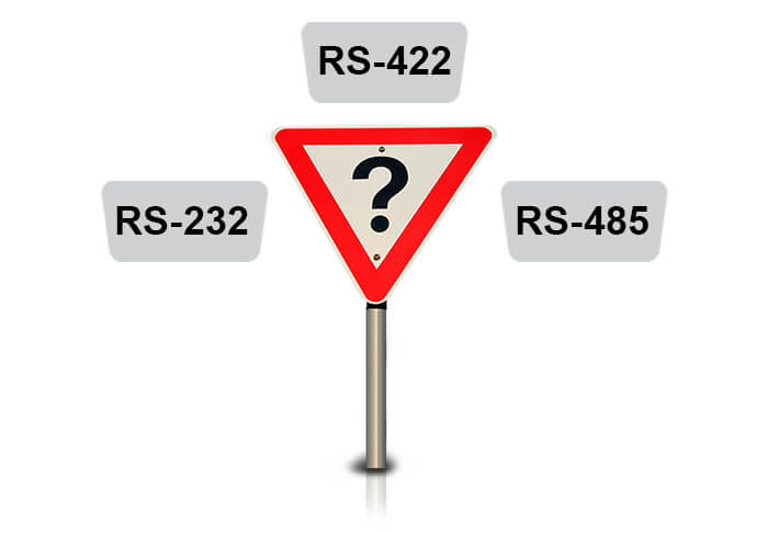
The RS232, RS422 and RS485 designations refer to interfaces for digital data transmission. The RS232 standard is better known as a normal computer COM port or serial port (although Ethernet, FireWire and USB can also be considered as a serial port). The RS422 and RS485 interfaces are widely used in the industry for connecting various equipment.
The table shows the main differences between RS232, RS422 and RS485 interfaces.
| Port name | RS232 | RS422 | RS485 |
|---|---|---|---|
| Transfer type | Full duplex | Full duplex | Half duplex (2 wires), full duplex (4 wires) |
| Maximum distance | 15 meters at 9600 bps | 1200 meters at 9600 bps | 1200 meters at 9600 bps |
| Contacts in use | TxD, RxD, RTS, CTS, DTR, DSR, DCD, GND* | TxA, TxB, RxA, RxB, GND | DataA, DataB, GND |
| Topology | Point-to-Point | Point-to-Point | Multi-point |
| Max. Number of connected devices | 1 | 1 (10 devices in receive mode) | 32 (with repeaters larger, usually up to 256) |
* For the RS232 interface, it is not necessary to use all contact lines. Typically, TxD, RxD and GND ground lines are used, the remaining lines are needed to control the data flow. You will learn more about this in the article.
Information transmitted via RS232, RS422 and RS485 interfaces is structured as a protocol, for example, the Modbus RTU protocol is widely used in the industry.
The RS232 interface (TIA / EIA-232) is intended for the organization of data transfer between the transmitter or terminal (Data Terminal Equipment, DTE) and the receiver or communication equipment (Data Communications Equipment, DCE) in the point-to-point scheme.
The speed of the RS232 depends on the distance between the devices, usually at a distance of 15 meters the speed is 9600 bps. At a minimum distance, the speed is usually 115.2 kbps, but there is hardware that supports speeds of up to 921.6 kbps.
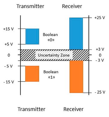
The RS232 interface operates in full-duplex mode, which allows you to send and receive information at the same time, because different lines are used for receiving and transmitting. This is in contrast to the half-duplex mode, when one link is used to receive and transmit data, which imposes a restriction on simultaneous operation, so in a half-duplex mode at one time, either the reception or transmission of information is possible.
In addition to the two receive and transmit lines, special lines for hardware flow control and other functions are available on the RS-232.
For connection to RS232, a special D-sub connector is used, usually a 9-pin DB9, and a 25-pin DB25 is used less often.
DB connectors are divided into:


There are three types of connection of devices to RS232: terminal-terminal DTE-DTE, terminal-communication equipment DTE-DCE, modem-modem DCE-DCE.
The DTE-DCE cable is called a "straight cable", because the contacts are connected one to one.
A DCE-DCE cable is called a "null modem cable", or in another way a cross-over cable.
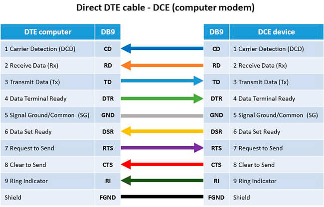
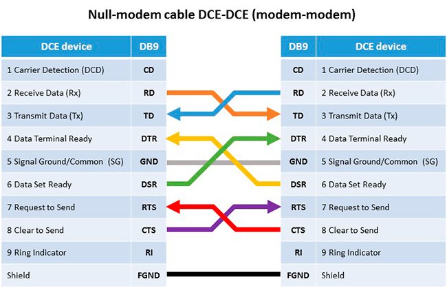
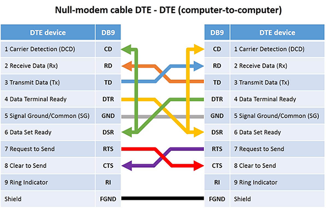
Table with pinout of DB9 and DB25 connectors.
| DB9 | DB25 | Designation | Name |
|---|---|---|---|
| 1 | 8 | CD | Carrier Detect |
| 2 | 3 | RXD | Receive Data |
| 3 | 2 | TXD | Transmit Data |
| 4 | 20 | DTR | Data Terminal Ready |
| 5 | 7 | GND | System Ground |
| 6 | 6 | DSR | Data Set Ready |
| 7 | 4 | RTS | Request to Send |
| 8 | 5 | CTS | Clear to Send |
| 9 | 22 | RI | Ring Indicator |
To work with RS232 devices, you usually need only 3 contacts: RXD, TXD and GND. But some devices require all 9 contacts to support the flow control function.
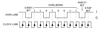
One message sent over RS-232/422/485 consists of a start bit, several data bits, a parity bit and a stop bit.
The start bit is the bit denoting the beginning of the transmission, usually 0.
Data bits - 5, 6, 7 or 8 bits of data. The first bit is the less significant bit.
Parity bit - A bit intended for parity checking. Serves for detecting errors. It can take the following values:
Stop bit - a bit indicating the completion of the message transmission, can take the values 1, 1.5 (Data bit = 5), 2. For example, a reduction of 8E1 means that 8 data bits are transmitted, a parity bit is used in EVEN mode and a stop bit occupies one bit.
In order not to lose data, there is a mechanism for controlling the flow of data, which allows to stop temporarily transferring data to prevent the buffer from overflowing.
There is a hardware and software control method.
The hardware method uses the RTS / CTS outputs. If the transmitter is ready to send data, then it sets the signal on the RTS line. If the receiver is ready to receive data, it sets the signal on the CTS line. If one of the signals is not set, no data transfer will occur.
The software method uses the Xon and Xoff characters (in the ASCII character Xon = 17, Xoff = 19) transmitted using the same TXD / RXD communication lines as the main data instead of the pins. If the data cannot be received, the receiver transmits the Xoff symbol. To resume data transmission, the Xon symbol is sent.
When using 3 contacts it is enough to close RXD and TXD with each other. Then all the transferred data will be accepted back. If you have a full RS-232, then you need to unzip a special stub. The following contacts must be connected in it:
| DB9 | DB25 | Connect |
|---|---|---|
| 1 + 4 + 6 | 6 + 8 + 20 | DTR -> CD + DSR |
| 2 + 3 | 2 + 3 | Tx -> Rx |
| 7 + 8 | 4 + 5 | RTS -> CTS |
The RS422 interface is similar to RS232. Allows you to simultaneously send and receive messages on separate lines (full duplex), but uses a differential signal for this, i.e. The potential difference between conductors A and B.
The data transfer speed in RS422 depends on the distance and can vary from 10 kbps (1200 meters) to 10 Mbps (10 meters).
In the RS422 network, there can only be one transmitting device and up to 10 receiving devices.
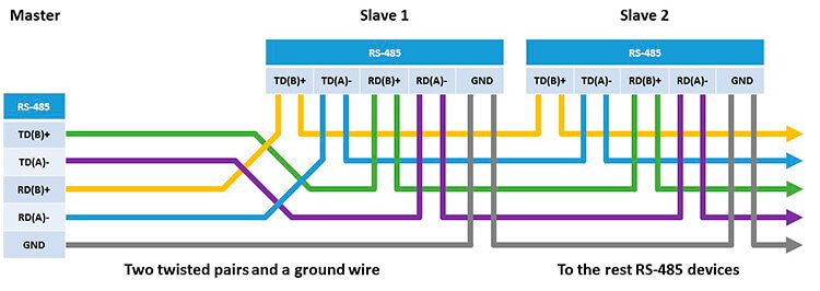
The RS422 line is 4 wires for data transmission (2 twisted wires for transmission and 2 twisted wires for receiving) and one common GND ground wire.
Twisting wires (twisted pair) with each other allows you to get rid of interference and interference, because the interference acts equally on both wires, and the information is extracted from the potential difference between the conductors A and B of one line.
The voltage on the data lines can be in the range from -6 V to +6 V.
The logical difference between A and B is greater than +0.2 V.
Logical 1 corresponds to the difference between A and B less than -0.2 V.
The RS422 standard does not define a specific type of connector, usually it can be a terminal block or a DB9 connector.
RS422 pinout depends on the manufacturer of the device and is specified in the documentation for it.
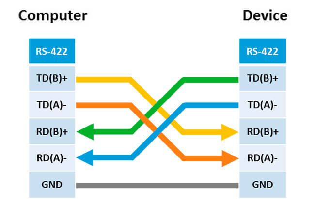
When connecting an RS-422 device, you need to make a crosshair between the RX and TX pins, as shown in the figure.
Because the distance between the receiver and the transmitter RS-422 can reach 1200 meters, then to prevent reflection of the signal from the end of the line, a special 120-ohm termination resistor or "terminator" is put. This resistor is set between RX + and RX-contacts at the beginning and end of the line.
To test devices with RS-422, it is better to use a converter from RS-422 to RS-232 or USB (I-7561U). Then you can use the software to work with the COM port.
In industry, the most common interface is RS-485 (EIA-485), because the RS-485 uses a multi-point topology, which allows you to connect several receivers and transmitters.
The RS-485 interface is similar to the RS-422 in that it also uses a differential signal for data transmission.
There are two types of RS-485:
In full duplex mode, you can simultaneously receive and transmit data, and in half-duplex mode either transmit or receive.
In one segment of the RS485 network there can be up to 32 devices, but with the help of additional repeaters and signal amplifiers up to 256 devices. At one time, only one transmitter can be active.
The speed of operation also depends on the length of the line and can reach 10 Mbit / s at 10 meters.
The voltage on the lines is in the range from -7 V to +12 V.
The RS485 standard does not define a specific type of connector, but it is often a terminal block or a DB9 connector.
The pinout of the RS485 connector depends on the manufacturer of the device and is specified in the documentation for it.
Connect RS485 devices with 2 contacts.

Connect RS485 devices with 4 contacts.
To match the line at large distances, the RS485 is also equipped with 120 Ohm termination resistors at the beginning and end of the line.
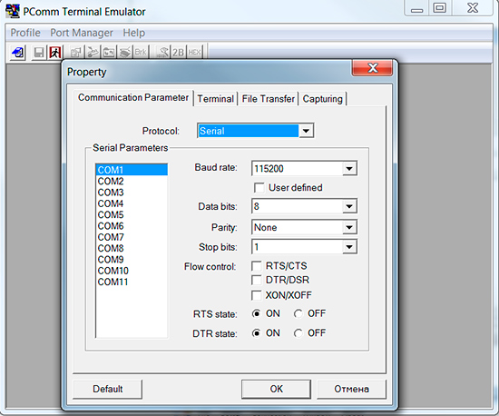
If you have a device with RS485 and you want to test it, the simplest thing is to connect it to a computer via a converter, for example UPort 1150, and use the special software described later.
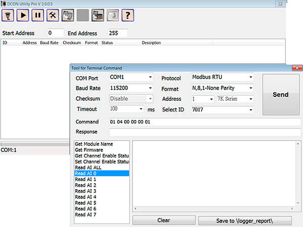
On the computer, the RS232/422/485 interfaces will be represented as a normal COM port. Accordingly, almost any programs and utilities for working with COM port are suitable.
Each manufacturer releases its own software for working with the COM port.
Manufacturer ICP DAS offers a utility DCON Utility Pro with Modbus RTU, ASCII and DCON protocols support.