Overview of serial to WiFi Converter USR-W610
USR-W610 is developed to replace USR-WIFI232-610 V2.
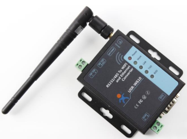
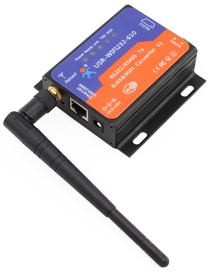
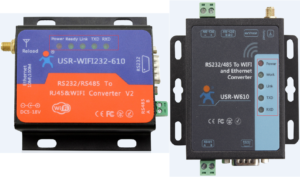
This manual is mainly to introduce differences between W610 and 610 V2. Product appearance diagrams as follows:
Photos of USR-W610
Photos of USR-W610
Basic parameters
|
|
USR-W610 |
USR-WIFI232-610 V2 |
|
Hardware parameters |
||
|
Serial port |
RS232*1 RS485*1 |
RS232*1 RS485*1 |
|
Working voltage |
DC 5V~36V |
DC 5V~18V |
|
Working Temp. |
-40℃~85℃ |
-40℃~85℃ |
|
Storage Temp. |
-40℃~125℃ |
-40℃~125℃ |
|
Storage humidity |
5%~95% RH |
|
|
Dimension |
86*82.5*25mm(L*W*H) |
84*84*25mm(L*W*H) |
|
Wireless parameters |
||
|
Wireless standard |
802.11 b/g/n |
|
|
Frequency range |
||
|
Transmitting power |
802.11b: +19dBm(Max.@11Mbps) |
802.11b: +19dBm(Max.@11Mbps)
|
|
802.11g: +18dBm(Max.@54Mbps) |
802.11g: +18dBm(Max.@54Mbps)
|
|
|
802.11n:+17dBm(Max.@HT20,MCS7) +17dBm(Max.@HT40,MCS7) |
802.11n: +17dBm(Max.@HT20,MCS7) +17dBm(Max.@HT40,MCS7) |
|
|
Receiving sensitivity |
802.11b: -89dBm(@11Mbps) |
802.11b: -89dBm(@11Mbps)
|
|
802.11g: -81dBm(@54Mbps) |
802.11g: -81dBm(@54Mbps)
|
|
|
802.11n: -73dBm(@HT20,MCS7) -71dBm(@HT40,MCS7) |
802.11n: -73dBm(@HT20,MCS7) -71dBm(@HT40,MCS7) |
|
|
Antenna |
SMA external antenna |
|
Hardware
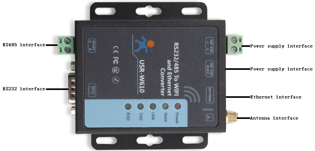
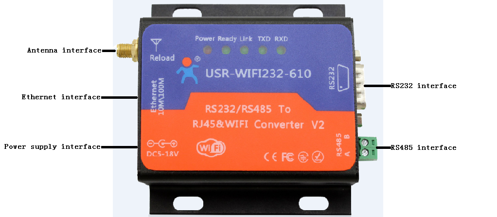
Interface
USR-W610 and USR-WIFI232-610 V2 interface diagrams as follows:
LED
USR-W610 and USR-WIFI232-610 V2 LED diagrams and LED functions as follows:
|
LED |
Description |
|
Power |
Power LED will light after powering the module successfully |
|
Ready(610 V2) |
Ready LED will light after module starting normally |
|
Work(W610) |
Work LED will blink every two seconds if module works normally. |
|
Link |
Link LED will light after establishing WIFI connection |
|
TXD |
TXD LED will blink when module sends data from serial side |
|
RXD |
RXD LED will blink when module’s serial side receives data |
Functions
|
|
USR-W610 |
USR-WIFI232-610 V2 |
|
WIFI |
||
|
WIFI mode |
AP/STA/AP+STA(in AP or AP+STA mode, AP interface supports at most 24 STA connections) |
|
|
Encryption mode |
WPA-PSK/WPA2-PSK/WEP |
|
|
Work mode |
||
|
Transparent transmission mode |
Support(Two sockets. Socket A supports TCP Server, TCP Client, UDP Server, UDP Client. Socket B supports TCP Client. TCP Server mode supports at most 24 TCP Client connections) |
Support(Two sockets. Socket A supports TCP Server, TCP Client, UDP Server, UDP Client. Socket B supports TCP Client. TCP Server mode supports at most 32 TCP Client connections) |
|
AT command mode |
Support |
|
|
https Client mode |
Support |
|
|
Serial port command mode |
Support |
|
|
Modbus TCP<=>Modbus RTU mode |
Support |
Don’t support |
|
Serial port |
||
|
Baud rate |
300, 600, 1200, 1800, 2400, 4800, 9600, 19200, 38400, 57600, 115200, 230400, 345600, 460800 |
|
|
Data bits |
5, 6, 7, 8 |
|
|
Stop bits |
1, 2 |
|
|
Parity |
NONE, EVEN, ODD |
|
|
Flow control |
Support hardware flow control |
|
|
Baud rate synchronization |
Support |
|
|
Features |
||
|
Search in LAN |
Support |
|
|
Identity packet |
Support MAC, user editable, USR Cloud identity packet |
Support MAC, ID, user editable, USR Cloud identity packet |
|
Usrlink |
Support |
|
|
Heartbeat packet |
Support |
|
|
Keep-Alive |
Support |
|
|
Websocket |
Support |
|
|
Web Server |
Support |
|